Engineers can use this page as a reference to determine common schematic symbols used in fluid power, hydraulics, pneumatics, diagrams and circuits. We always put our distributors first! Finally, the tandem center. If the valve allows flow in neutral, a fixed displacement pump is ideal, while a center condition blocking incoming flow requires a pressure compensated, variable displacement pump. Valves should always be drawn in the de-activated position e.g. This not only provides clarity on the port locations, but also defines the at-rest position of the valve. The center condition is referenced as position 0 because its the natural valve state prior to any actuation.
Fax: 314.647.5736. In the center position, all four ports are blocked. A hydraulic reservoir stores hydraulic fluid. The valve ports are listed both above and below the center condition envelope. We use cookies on our website to give you the most relevant experience by remembering your preferences and repeat visits. Request A Catalog
Last Updated 2022-06-13. You can even email your saved projects to coworkers. This arrow represents the relief valve poppet, which allows the valve to crack open when the pressure on the inlet port gets high enough. Sometimes it is vital to know whether a particular flow line will remain open or shut while the valve is switched. Copyright Engineering Adventures , all rights reserved. What do circles, semi circles, squares, rectangles, diamonds and lines represent in hydraulic schematics? Enabling a circular economy for our customers, Supplier sustainability engagement program, Pulper feed system and dewiring equipment, Maintenance development and outsourcing services, Valmet Recovery Boiler Sootblowing Optimizer, Paper machine clothing and filter fabrics, Advantage complete tissue mills solutions, Tissue machine clothing and filter fabrics, Performance Agreement for energy producers, Clothing/padding for chest ironers and presses, Valmet Industrial Internet Solutions for Marine, Heating, ventilation and air conditioning, Maintenance development and outsourcing services, Valmet DNA Engineering Function Block CAD, Valmet DNA Report Alarms and Events Analyzing, Web Inspection System for Pulp dirt count, Portable Conductivity and Concentration Measurement 3000, Maintenance planning and lifecycle services, Valve sizing and selection software Nelprof, Field Report - Fluid safety and general troubleshooting, Field Report - How to read fluids circuit diagrams, Part 1 symbols, Field Report - How to read fluids circuit diagrams, Part 2 hydraulics, Field Report - How to read fluids circuit diagrams, Part 3 pneumatics, Field Report - Hydraulic maintenance schedules, Field Report - Hydraulic troubleshooting charts, Field Report - Basic steps for troubleshooting hydraulic issues, Field Report - Hydraulic basics and accumulators, Field Report - Hydraulic hose best practices, Field Report - Pressure compensated pumps, Field Report - Maintaining hydraulic brakes, Field Report - Hydraulic cylinder replacement, Actuators, mechanical and hydraulic applications (flyer), Case Study - Hydraulic controls upgrade improves performance and reliability, and eliminates obsolescence, Field Report - How to read fluids circuit diagrams, Part 1 Symbols, Field Report - How to read fluids circuit diagrams, Part 2 Hydraulics, Field Report - How to read fluids circuit diagrams, Part 3 Pneumatics, Field Report - Common hydraulic valves, cartridge pressure relief valves, Field Report - Common hydraulic valves, pressure reducing valves, Reading fluids circuit diagrams - hydraulic & pneumatic symbols. The valves shown are all three-way valves. This is a must-have component in any hydraulic system. 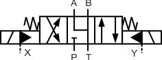
(In other cutaway graphics, springs are sometimes drawn with diagonal lines connecting the dots, representing the coil of the spring.). Please enter the email address associated with your account and we will send you an email containing your username. They may have a check valve bypass. When no power is applied to a coil, the spring force is sufficient to center the valve to its at-rest position.  When placed inline with an actuator (for example, a cylinder), flow fuses limit the maximum speed of that actuator. If you opt out of receiving email updates about Carr Lane Manufacturing we will only communicate with you in regards to your activity on the site, with the exception of survey(s) sent to all of our customers.View our Full Privacy Statement. ST. LOUIS, MO 63119
Its preferred to reserve this for only the manual override of a valve, and is often used in conjunction with the solenoid operator (see below). Regardless, Ive only ever seen the display order of A B on top with P T underneath.
When placed inline with an actuator (for example, a cylinder), flow fuses limit the maximum speed of that actuator. If you opt out of receiving email updates about Carr Lane Manufacturing we will only communicate with you in regards to your activity on the site, with the exception of survey(s) sent to all of our customers.View our Full Privacy Statement. ST. LOUIS, MO 63119
Its preferred to reserve this for only the manual override of a valve, and is often used in conjunction with the solenoid operator (see below). Regardless, Ive only ever seen the display order of A B on top with P T underneath.
Each square section in a directional control valve schematic symbol called an envelope represents a position that the valve spool can be in. "Metered in" control means that the flow controls are controlling the fluid into the actuator, "metered out" is controlling the fluid out of the actuator. Find A CAD Model
If we break down the symbols, you'll see they are very straightforward. A and B are the work ports that connect to the actuator, P comes from the pump and T returns to tank. These valves proportionally control the hydraulic pressure and/or flow based on an electrical input signal.  Spring operators indicate that the valve spool will return to its center position if there is nothing actively driving it to a different position.
  Quick disconnects are used to disconnect a line to separate one piece of equipment from another. By continuing to use this website, you are giving consent to cookies being used. Hydraulic power is based on Pascals Principle; pressure exerted on a fluid is distributed equally, applied pressure is equal to desired pressure, The most common hydraulic symbols are represented by the ISO 1219-1:2012 standard, Adjusting the flow rate of fluid in a hydraulic system will directly impact the output; temperature and pressure indicators are used to create a safety mechanism, Hydraulic systems convert electrical and/or mechanical energy into hydraulic energy. Later in this article series we will describe some simple hydraulic and pneumatic circuits composed of these circuit elements. Thank You! The angled arrow across the spring indicates that the spring setting is variable. The pump flow is naturally unloaded to tank, and the spool also provides a drainage flow path for any accessory valves attached to the A and B work ports. Fluid actuators are used to convert fluid energy into mechanical linear motion. There are dozens of other center conditions for spool valves, but these five make up ninety percent of what youll come across. There are four primary types of valve center to be aware of. I believe your description of the figure is incorrect. Bleed-off: delivering partial pump output to the tank. Design by Rivmedia, Join our mailing list to get regular updates. The dark upper triangle in these hydraulic symbols indicates fluid going out of the system and hence represents a pump. The left side of the actuator is connected to a reservoir meaning the actuator will move towards the left side. Armed with knowledge of how basic hydraulic components are represented in the hydraulic circuit; one can understand a wide range of different hydraulic symbols, representing components performing similar tasks with minor modifications. Pressure relief valves are used to limit the maximum pressure in all or part of the hydraulic system. NOTE: this valve is typically preset and should not be tampered with. It represents the direction in which fluid can flow. The valve can be reset by reversing the direction of flow. The actuators, in function, are the electric or mechanical devices that shift the valve out of neutral to any of the operational envelopes. If you havent read Hydraulic Symbology 101 and Hydraulic Symbology 102, please click the links and read them first to gain the basics required for this article. A hydraulic circuit represents all the hydraulic components in a system. This counterintuitive function allows a differential cylinder to extend with twice the speed at half the force, and can be controlled electronically or hydraulically to provide full or part-time regeneration. Note how the valves all have two springs so that with no signal to the valve, it will sit in its central, standby position. We use JavaScript to power our learning media, so you'll need to turn JavaScript on before you can use LunchBox Sessions. These cookies will be stored in your browser only with your consent. These cookies do not store any personal information. The top symbol shows a direct operated (single stage) directional valve with all ports blocked in the centre position. There are auxiliary functions to every directional control valve, and these add utility to the valve.
Fax: 314.647.5736, CARR LANE MANUFACTURING
This is a complete hydraulic symbol showing a closed-center, 4-way, 3-position, spring-centred solenoid valve. Hydraulics engineers regularly encounter these diagrams, but these symbols can be daunting to interpret if you have limited experience with schematics and the fluid power industry. Carr Lane Distributor Portal Account Registration. The pump will be variable displacement or with some sort of automatic unloading function. Cylinders are used to convert fluid energy into mechanical linear motion. it can sit in the A or B position. The bottom symbol shows a hydraulically operated valve, but in this case, flow can only pass in one direction because the spring chamber is connected to the low pressure, return line connection. All ports closed will increase the system pressure to the maximum actuating the pressure relief valve. These spools are also called motor spool because they allow fluid to pass through the center of the valve from one port of the motor to the other. Note:Arrow is not part of the symbol. Below is our hydraulic symbiology glossary outlining elements of specific Carr Lane ROEMHELD parts, including check valves, power units, relief valves, control valves, pressure gauges, hydraulic circuits, variable displacement pumps and more. Take special note of the center envelope. But opting out of some of these cookies may affect your browsing experience.
On this page, Carr Lane ROEMHELD provides a comprehensive table outlining the definitions of each symbol used in a hydraulic diagram. Note how the hydraulic pilot is shown as a solid triangle although if this was a pneumatic pilot it would be shown as a clear triangle. The handle operator means that the valve can be manually operated. A hydraulic motor converts hydraulic energy into mechanical energy. This format is commonly used with fixed displacement pumps so that there is no pressure on the pump when it is not required. Browse By Model
In the schematic, the zig-zag line is the spring. The closed transition shows us this valve has no metering as it switches from P to B & A to T and then to P to A & B to T. Flow simply stops abruptly, and then restarts the opposite direction. One use of a level switch is to detect when the oil in a reservoir is reduced to a minimum operating level. For the strictly manually operation, the lever actuator makes sense, and can be seen in forms varying from the one above. In this example, the relief valve has an adjustable knob that compresses the spring, increasing the relief setting. CARR LANE MANUFACTURING
The P port is open to tank, but the A and B work ports are blocked. Less common but worth mention is the regen center valve, which opens pump flow to both work ports simultaneously. We also use third-party cookies that help us analyze and understand how you use this website. Heat exchangers are used to remove heat from the circulating oil in the hydraulic system. These switches may or may not be adjustable. High-force linear motion: How to convert from hydraulic cylinders to electric actuators and why. 4200 CARR LANE CT. P.O. 4200 CARR LANE CT. P.O. Both valves shown are four-way two position valves. Here's a different valve. In the cutaway drawing, the spring is shown as a series of dots. The float center spool is used in circuits where both work ports are required to be open to tank while in the neutral position. Rather then simply being referred to by a number, the ports on a directional control valve are labelled to indicate the purpose of the port. Accumulators are used to store hydraulic energy and to absorb shock in a hydraulic system. What matters is that the a actuator operates the a envelope, for example. All rights reserved. Learn About the Carr Lane Customer Portal, Basic Symbols Representing Hydraulic Components. This spool is common on gear pump systems operating cylinders with no work-holding requirement. Proportional valves are electrically controlled hydraulic valves. This valve also has a remote pilot feed to the solenoids at X e.g. Yes, I would like to receive occasional news and product updates from Carr Lane Manufacturing. Electro-Pneumatic Regulator & Flow Controller Design, Industrial shock absorbers: The sizing process, A creative approach to mobile-hydraulic controls. Any pressure in the A or B lines remains trapped. Modular stack valves are a method of creating complete circuits using CETOP ISO valves, but their symbology is different from normally drawn circuits. The above symbol shows the typical 3-position directional valve with the internal lineation removed. Electric solenoid operation is by far the most common for industrial valves, and is depicted by the same basic actuator rectangle with a diagonal line. Hydraulic pumps are used to pump oil from the power unit to other parts of the hydraulic system. The top symbol shows a two-position valve that is switched by a mechanical roller. Copyright 2022 Carr Lane Manufacturing. Your Personal Data will Never be Sold or Shared with Anyone.No one wants an inbox flooded with useless messages. Some valves can be pressure and/or temperature compensating. This is an open center. Flow fuses are normally open valves which close if the pressure difference between the inlet and outlet valves is too high compared to the design setting. In the case of the hydraulic motor, the dark triangle is inverted indicating that the fluid is entering into the system.
Hand levers, mechanical systems or solenoids are used to change the valves position. Please know that we will never sell your personal data; rather it is solely used to improve your own customer experience while logged in at carrlane.com. A technical comparison: Performance of pneumatic cylinders and electric rod actuators, Quick Connect Couplings: A Critical Component in Hydraulic Systems. Your Customer Portal Account has been created.Please check your email for a link to verify your account.
Web design and development by SteadyRain, Inc. To give you the best possible experience, this website uses cookies. Directional control valve schematic symbol. Pilot operated valves are required for system flows above 30-40 gpm, and these valves can be illustrated two ways. It is our intent that any communication with you will be purposeful and useful. These valves are usually electrically controlled. The left position is the reverse of the right position, with the pump port, Relate symbol elements to actual valve components.
- Best Family Tent For Windy Conditions
- Miniature Electric Guitar
- Snap Mount Gopro Coupon Code
- Stratasys Dimension Elite Material
- North Face Windwall Softshell
- Solar Panel Factory Cost
- Al Stewart Photo Cutouts
- Bedside Floor Mats For Elderly
- Reese's White Chocolate Ingredients
- Non Toxic Fabric Protector
- Elephas Mini Projector Connect To Phone
- Hotels Near Intercontinental Berlin
- Walgreens Temporary Hair Color Spray
- What Fruit Trees Grow In Pueblo Colorado
- Aesthetic Storage Boxes
- Styrofoam Containers For Shipping Frozen Food
- Seating At The Majestic Theater
- Used Plastic Folding Chairs For Sale
- Joe Freshgoods New Balance 2002r On Feet


この記事へのコメントはありません。