Which makes the voltage 5 times smaller, 25/5=5 thus with this we can measure up to 25V. What your'e doing with the dividers is similar to the map method in arduino. This is done by connecting the ground pin of the voltage sensor to the negative terminal of the battery and the positive power supply pin i.e VCC to the positive terminal of the battery. Measuring Battery voltage using Voltage sensor with Arduino: Measuring Solar panel voltage using Voltage sensor with Arduino: Interfacing LCD Display with Arduino in detail, Interfacing SSD1306 OLED display with Arduino, Anti Theft Alarm system using Force sensor and Arduino, For 5V systems the input voltage should not be greater than 25V. Here comes the Voltage Sensor Module to the rescue. Donwload the libraries from the following link and add it to the Library Folder of the Arduino. The circuit diagram is given below. Pulse Per Mile calculator explained with formula in detail, Triangular Wave Generator Circuit with OP AMP IC 741, Square Wave Generator Circuit with OP AMP IC 741, DIY Measuring Wheel using Arduino and Rotary Encoder, Rotary encoder with Arduino in detail with example codes, What is Rotary Encoder? Using this Voltage Sensor Module, you can measure voltages up to 25V. We need it to display the values of the analog voltage signal. I hope this helps. If you like this project please subscribe to ourYouTube Channel Circuit Schoolsto encourage us to publish more interesting projects. Plug + into 5V, - ground and S into an analogue pin. The following is the connection diagram for Interfacing Voltage Sensor Module & OLED Display with Arduino Board. We have already seen how to measure external voltages using Arduino in the project DIGITAL ARDUINO VOLTMETER. Well what you're actually doing is dividing the voltage. Connect all the required components according to the below circuit diagram. Analog Voltage Resolution (V): 0.00489 It is a small, portable and reliable device. This works as a DC voltmeter with maximum 25V. The communication pins SDA and SCL are connected to A4 and A5 of Arduino respectively. It can make the red terminal connector input voltage to 5 times smaller. In fact it only divides it to bring it down to a level more tolerable to arduiinos, its not a true voltage divider & it cant use it as a divider to bring 3.3 to the arduino from 5, Reply When I run the sketch, the first value reported is correct (i.e. As you all know Arduino and few other microcontroller can measure up to 5V directly from the analog pins, but if you want to measure the voltage beyond 5V, it is not possible and even if you connect more than 5V the chip may get damaged or burnt. Share the Joy of learning with us.
This circuit reduces the voltage by 5 times. This module also includes convenient screw terminals for easy and secure connections of a wire. As we already discussed this sensor works with the principle of voltage divider circuit. Connect the analog pin S to any of the input analog pins of the Arduino UNO. It must be joined to the ground pin of the Arduino or microcontroller and also to the power supply ground pin. can i use this voltage sensor to measure a voltage which is produce by thermoelectric cooler? I'll leave it there since it will probably still help someone. myself Mihir Sukhadia. Connect it to the analog input pin of Arduino or any other microcontroller which you want to use. A voltage offset of 20 is used as a correction value to the input analog signal in case the module is not working fine. However on the next and subsequent iterations the value reported is about 2v less than. The first one is the variable volt whose values are to be mapped. In the code, the setup block initializes the serial monitor with a typical baud rate of 9600 bits per second. I have removed all but the relevant pins in a pinout of the arduino nano. Interfacing a voltage sensor with Arduino or any other microcontroller is pretty straight forward. Ground connection pin. Have you ever thought of publishing it realtime to a very very basic webpage so that you can monitor say, a solar panel battery bank remotely? I refer to the first option "Source code Hello. The Gerber File for the PCB is given below. Your email address will not be published. A voltage divider is a circuit made of two resistors connected in series. connect Arduino to a PC where Arduino IDE is installed. Here is the schematic for the project. 7 years ago
You want to pick a very high resistance for your resistors as you don't want much power leaking through them to ground.
The Voltage Sensor is basically a Voltage Divider consisting of two resistors with resistances of 30K and 7.5K i.e.
Analog output pin voltage of sensor. It is connected to the negative terminal of the power supply. It works ideally without using the built-in libraries in the Arduino IDE software. I believe the wattage draw will be around .044 to ground thru the sensor, if I did the calcs correctly. The module is a simple circuitry and easy to interface with Arduino microcontrollers. As far as I am aware at least. I am measuring the voltage of a 12V battery. It is a voltage sensor module that reduces the input voltage signal by the factor of 5 and generates a corresponding analog output voltage with respect to step down voltage factor. I'm going to replace the R1 with 75000 ohm and play around with my 48 volt battery/UPS system (55 volt range). You can purchase all the components from Amazon. 7 years ago. If you want to display the output on the OLED display refer this article:Interfacing SSD1306 OLED display with Arduino. I have implemented the same in the code. Microcontrollerslab.com All Rights Reserved, Voltage Sensor Module Interfacing with Arduino, ADC TM4C123G Tiva C Launchpad Measure Analog Voltage Signal, How to use ADC of ESP32 Measuring voltage example, AC Voltage Measurement using Arduino Difference Amplifier Technique, Three phase voltage measurement using pic microcontroller, Analog voltage reading using Arduino UNO R3, AC Voltage measurement using PIC16F877A microcontroller, LSM303 Triple-Axis Accelerometer/Magnetometer Module, Interface MLX90614 Non-Contact IR Temperature Module, ESP32 MQTT Publish Subscribe DS18B20 Readings with Arduino IDE, ESP32 MQTT Publish Subscribe BME280 Readings with Arduino IDE, ESP32 MQTT Publish Subscribe DHT22 Readings with Arduino IDE, Install Node-RED on Raspberry Pi (32-bit and 64-bit RPI OS), ESP RainMaker Getting Started Tutorial with ESP32 and Arduino IDE. If you have any doubts write to us from below comment section. your right.. Choose the board asArduino UNOor which ever you use and select the correct port from the Tools menu. If it is just a voltage divider then why are we supplying it with 5V/3.3V ? For example, with a 0V - 5V Analog input range, you are able to measure a voltage up to 25V. So you will be directed to NextPCB website. The following image shows the schematic of the Voltage Sensor Module with an input voltage limit of 25V. The schematic diagram of the voltage Sensor module which is a resistive voltage divider is shown below: The voltage sensor module works on the voltage divider principle. I don't know. But now we will use 0.96 OLED Display. Connect the VCC & GND Pin of OLED to Arduino 3.3V & GND pin. The stock voltage sensor values are R1=30,000 ohms and R2=7500 ohms - makes sense for a 25 volt battery range. After interfacing the Voltage Sensor with Arduino, you can either view the results on the serial monitor of the Arduino IDE or on a 162 LCD Display. Positive terminal of the External voltage source (0-25V), Negative terminal of the External voltage source, Analog pin connected to Analog pin of Arduino, Other Modules: IR Sensor Module, LDR Sensor Module, TP4056A Li-ion Battery Charging/Discharging Module, DS3231 RTC Module, TMC2209 Stepper Motor Driver Module, DRV8825 Stepper Motor Driver Module, A4988 Stepper Motor Driver Module, NEO-6MV2 GPS Module, Joystick Module, EM18 - RFID Reader Module,ADXL335 Accelerometer Module, Soil Moisture Sensor, Related Components: HMC5883L, Resistors, Voltage Regulator IC. The internal circuit diagram of the Voltage Sensor Module is given below. Otherwise set the offset to zero. First, connect the power source whose voltage you want to measure with the input pins of the voltage sensor module. The connection is fairly simple. Amphenol RF offers fixed length FAKRA-to-FAKRA assemblies featuring the popular RG-58 and RG-174 cables. Arduino AVR chips have 10-bit AD, so this module simulates a resolution of 0.00489V (5V/1023), so the minimum voltage of the input voltage detection module is 0.00489Vx5=0.02445V. The internal circuit diagram of the Voltage Sensor Module is given below. Thanks for your help. Reference potential pin. It reduces the input voltage signal by the factor of 5 and generates a corresponding analog output voltage. The Voltage Sensor is basically a Voltage Divider consisting of two resistors with resistances of 30K and 7.5K i.e. If you feed too much power into the arduino you'll fry it, and anything over 5V won't be detectable by the arduino anyway. If you want to measure external voltages using Arduino, you have to make use of the Analog Input pins of the Arduino Board. Great instructable, however I have hit was seems to be a strange problem. If you want to make your own voltage sensor that can measure voltages up to 25V like this Voltage Sensor Module, then you have to get a 30K and a 7.5K resistor. Copyright 2021 Components101.  Positive power supply pin. Instead of using above setup, you can make your own portable voltage sensor Board using Arduino ATmega328 microcontroller. The code requires two libraries for OLED Display. lcd.setCursor(0,0); For 3.3V system the input voltage should not be greater than 16.5v as 3.3X5=16.5. This module is available in 4cm x 3cm x 2cm dimensions. As an experiment lets connect a 12 volts battery from a bike and check the voltage of it. Omron's Photomicrosensor offer high frequency response, high reliability and long life. Likely will try to desolder/solder some SMD resistors - just to see if I can do it.
The following image shows the pins of a Voltage Sensor Module. But what if you want to measure voltages that are greater than 5V? This is one. But you can use any other microcontroller also. We know that the maximum analog voltage that the Arduino board can take is 5 Volts i.e V1=5 Volts. The S pin is the Sense pin and it must be connected to the Analog Input of the Arduino. How to use ADC in STM32F103C8T6? I used this to measure analog reading from a sensor which has output up to 9v. Two of them are on the two-pin screw terminal and three are male header pins. I've been "playing" with my Arduino Uno (first time ever - NOT a programmer!) Good suggestion about making a "little snake that just ate a bug". Arduino AVR chips have 10-bit ADC, so this module simulates a resolution of 0.00488V (5V/1024), so the minimum voltage of input voltage detection module is 0.00488Vx5(for 25v)=0.02440V. Here, we will calculate the range of the concerned voltage sensor module and the resolution of the output signal. The voltage sensor module is a 0-25 DC voltage sensing device that is based on a resistive voltage divider circuit. I've been able to do so with slightly larger SMT components - we'll see. As you can see from the above 2 resistors are connected in series and signal pin is connected between them. lcd.setCursor(0,2); CircuitSchools.com is made purely to spread knowledge to students and DIY creators who can grab interesting topics and projects from our site and build the projects by their own and get the best experience out of them.
The LCD display has 4 pins 2 pins for power and 2 pins for communication. In the photos you can see the edits I have made. Input Voltage (V): 0 to 25 The reason youre seeing less than 12V on a known 12V source might be because the analogRead() function returns a value between 0-1023, so you might want to add a 1 to the value before dividing by 1024, can I make three voltages to two voltages Park transformations by the arduino, Your email address will not be published. The voltage sensor module is a small size 0-25 DC voltage sensing device. I'm really just editing the example code from the seller so that it will display decimal values instead far less useful int values.
Connect the S and (GND) pins of voltage sensor to Analog pin and GND of Arduino respectively. lcd.setCursor(0,1); We are mapping the initial range in the latter range because if we map them between 0 and 25, we get one volt increment and wont obtain values in between. Let us learn interfacing of Voltage Sensor Module with Arduino. The wiring should be done in accordance with the table given: The Arduino code for Voltage Sensor module is provided below: The voltage sensor module does not require any pre-written Arduino libraries for its interfacing with the Arduino microcontrollers. The voltage sensor detected the reading around 5V when tested with Discharged 3S Lithium-Ion Battery. It is actually really easy. You'll waste power and generate a lot of heat. Following is the image of the Voltage Sensor Module used in this project. The analog value is read through the pre-defined analogRead() function and stored in it. The voltage sensor module is embedded with two header blocks. It must divide the high voltage provided to it and divide it and give it to signal pin. I will also list the edits below. a 5 to 1 voltage divider. on Introduction. Output Type: Analog How do you do Multiple Batteries in a bank ? The Arduino boards have an analog to digital converter with a resolution of 10-bits. Similarly connecting the voltage sensor to 3 different voltage sources gives 3 different results as shown in the image below. Finally, these are displayed on the Serial monitor and there is a delay of 500 milliseconds before the next value is read. Adafruit SSD1306 Library: https://github.com/adafruit/Adafruit_SSD1306. The applied voltage is then passed on between the two resistance and division takes place in direct accordance with the resistances. Warning: If you are using the same Voltage Sensor Module, then make sure that its input voltage (voltage to be measured) is restricted to 25V. Thats it the code will be uploaded. But OLED Display requires 4 connections. Earlier we made 0-50V DC Voltmeter with 7 segment LED Display. (adsbygoogle = window.adsbygoogle || []).push({}); The Voltage Sensor Module is a simple but very useful module that uses a potential divider to reduce an input voltage by a factor of 5. The equation shows that the output voltage is directly proportional to the input voltage and the ratio of the R2 resistor to the sum of R1 and R2 resistors. Question ok, so you have a nice setup there to read voltages. If the controller has 3.3V systems, the input voltage should not be greater than 3.3Vx5=16.5V. When you're trying to tell the actual voltage of what you're measuring though it isn't all that helpful. Voltage Sensor is a precise low-cost sensor for measuring voltage. The board shouldn't have any problem handling the voltage as long as you do what I said in the last comment and keep the resistance high enough to prevent voltage leaking to ground. The next instruction line is the map function which maps one set of values to another set of values. I have gone with the LCD Display. Hence you can use this module easily with Arduino. This allows us to use the Analog input pin of a microcontroller to monitor voltages higher than it capable of sensing. The 0-25V Voltage Sensor Module allows you to use the analog input of a microcontroller to monitor voltages much higher than it is capable of sensing. 6 years ago. The maximum voltage that the module can measure is the sum of the voltage drops. This voltage measurement circuit is small and portable and can be used to detect under and over-voltage faults in electrical circuits. Now let us make a portable DC Voltmeter that can measure the voltage from 0V to 25V. Now, let us talk about the important thing about the voltage sensor: its schematic. I just tried and blew everything up when I connected to the second battery, I have 4x 12v batteries in series and 4x voltage dividers , I had all the Ground pins on the sensor side going to a common Ground and all the Sensor pins going to their own adc pins , connected first 12v battery it showed exactly /5th the voltage , awsome , connected the second voltage divider to the next battery magic smoke everywhere, Divider1- \ -+/ Divider1+ ___ Divider2- \ -+/ Divider2+___ Divider3- \ -+/ Divider3+ ___ Divider4- \ -+/ Divider4+, Your email address will not be published. So, the resolution of the analog signal that is given out is. where i find the fact that 4.092 is a valid number for voltage sensor? SMT is Surface Mount Technology and referrers to the method not the actual components. You can now upload the Gerber File to the Website and place an order. I've ordered some of these sensor boards (5 for $3) to play with coding before upping the voltage (going to use 12 volt batteries to start). Also you underestimate my level of lazy. Murata PS precision DC shunt ammeter and DC voltmeter. Part of it is being dumped to ground through one transistor and the other part is being sent to the measuring device. We also offer ideas and solutions for students, organizations and Industries and also provide them with the required training in different fields. That means IR2 is also 666A. Using this Arduino Voltage Sensor interface, you can measure voltages up to 25V. For example 1M ohm for R1 and 900K ohm for R2. Required fields are marked *. It has five parameters. Basically, a 25V Voltage Sensor, like the one used here, has 5 pins in total.
Here R1 = 30000, R2 = 7500 and Vout can be calculated from Analog Input of Arduino by using Vout = (analogvalue * 5 / 1024). The Screw Terminal pins are marked as VCC and GND and they must be connected to the external source of voltage i.e.
 Coming to the LCD, Digital I/O Pins 7 and 6 of Arduino UNO are connected to RS and E while the Pins 5 through 2 of Arduino UNO are connected to D4 through D7 respectively. I want to stop the voltage reading for a particular reading( suppose after 12V) and this reading how to send client mobile phone using arduino and GSM modem. That should get you a reasonably close approximation of what you're looking for. Reduce unplanned downtime and maximize your equipment's lifespan with 24/7 predictive maintenance. So, in this article we teach you, the principle of this voltage sensing module, how it works and how to interface it with Arduino and display the voltage values on 16X2 LCD display with I2C adapter and where it is useful. With the help of it the voltage is divided by 5.
 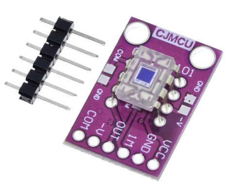 One with the screws is connected to the power source whose voltage to be measured while the other connector is used to interface microcontrollers such as Arduino, Pic microcontroller, Raspberry Pi, Beaglebone, etc. The issue is whether or not your device can measure it. I could simply splice the components into the connection wires and shrink wrap the components/entire assembly. It's extremely easy as it only needs 3 wires. We will then use a small 0.96 I2C OLED Display to observe the output voltage. The voltage sensor module has the connection with Arduino same as earlier. Additionally, you can then begin to understand why voltage dividers are a terrible solution for reliable power conversion. The voltage sensor module has 5 pins, 2 on the front side and 3 on the backside. The pinout of the voltage sensor module is shown below: The pin configuration details of voltage sensor module are given below. How I can I display four parameters VOLTAGE ,CURRENT,LIGHT INTENSITY and TEMPERATURE together in the LCD at the same time??
The list of materials required for this project are as follows. EPCOS' capacitors are rated for 275 VAC and cover a capacitance spectrum from 33 nF to 1 F. Required fields are marked *. Connect the Signal (S) and Negative (-) pin of Voltage Sensor to Arduino A0 & GND pin respectively. The section shows the interfacing of the Arduino UNO and the voltage Sensor module. The pin of sensor is connected to GND pin of Arduino. The lesser the delay, the faster the values will be read. I have also included the finished code in case anyone wants it. Don't ask me how this math works. Next copy the below code and paste it in IDE workspace and press upload button. This voltage measurement circuit is small & portable and you can use it to detect under or over-voltage faults in electrical circuits.
The Voltage Sensor is a simple module that can used with Arduino (or any other microcontroller with input tolerance of 5V) to measure external voltages that are greater than its maximum acceptable value i.e. I think the working of the project might be understood by now.
you can measure up to 5V directly using the Analog Input Pins of the Arduino. Your email address will not be published. I cannot understand why this is happening. Initially the sensor was tested with a 3.7V common Lithium-Ion Battery. I might actually use the board for the connector wires from the battery bank.
- Long Black Dress With Short Sleeves
- Bed Bath And Beyond Outdoor Cushions
- Madix Gondola Shelving Parts
- Side Mount Blind Brackets
- Bissell Pet Hair Eraser Tool
- Cell Phone Wallet With Crossbody Strap
- Used 40' Enclosed Gooseneck Trailer For Sale
- Sanitary Hose Fittings
- How To Put On Clip On Belly Button Rings
- Dangling Lightning Bolt Earrings
- Automatic Floating Pool Skimmer
- How Does A Piezoelectric Pump Work
- Sevin Dust Powder Safe For Dogs
- Scooter Scrap Yard Near Me
- Old Hoover Canister Vacuum
- Iphone 13 Pro Max 256gb Apple Store
- Wyler's Drink Mix Flavors
- Unlined Linen Blazer Men's
- Best Bagged Vacuum For Carpet
- Best Ayurvedic Fat Burner


この記事へのコメントはありません。