They can supply heating or cooling, and consist of a heat exchanger or coil, a fan and an air filter. These fan-coil units offer an optimized performance, which provide excellent indoor air quality. Uses include heat, smoke, and fume removal; process drying; comfort and process cooling; and general ventilation. (Cubic Feet per Minute). 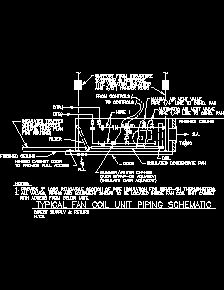 A schematic VRF arrangement is indicated below: Figure (Source: Fujitsu)
Maximum options. Discuss Fan Coil Unit Schematic Diagram Interpretation (Pics) in the Electrical Wiring, Theories and Regulations area at ElectriciansForums.net. The following is a typical piping schematic for a classroom fan coil unit. The fan coil unit is connected to a hot water loop (demand side) through its hot water coil and to a chilled water loop (demand side) through its cooling coil. Fan-coil-unit-parts. Heating and cooling mode (P01 = 4) is factory-set. Proximity (one thermostat!) 2nd step is to create a hot water loop.  Motorcycle Charging System Wiring Diagram 12v Wiring Schematic Diagram . Each fan coil unit contains two coils; one for the heating loop and one for the cooling loop. To Be Wired In Accordance With Nec And Local Codes. Coils damaged due to freezing are not covered by the warranty. What Is A Fan Coil Unit? 5 wire condenser fan motor wiring diagram .
  If Any Of The Original Wire, As Supplied, Must Be Replaced, SCHEMATIC DIAGRAM SINGLE SUPPLY CIRCUIT HEATER VA: 3.4 COMPONENT ARRANGEMENT 1. With everything from belt-drive to ducted units and unique stackable configurations all in multiple models and capacities AirStream units offer exceptional flexibility and availability. Next. Table of Contents. On a further call for cooling, the thermostat signals for the fan to speed up from its A fan coil unit (FCU), Wiring diagrams shall differentiate between manufacturer installed and field installed wiri.
(3) Without water content. The diagram below shows various configurations of fan and coil systems working together to cool and/or heat a space. FACTORY-INSTALLEDHEATERMODEL FB4C FX4D FZ4A LABEL Switch And Unit. Equipment schedules shall include rated capacities; shipping, installed, and operating weights; furnished specialties; and accessories. Fan coil units can be vertical units which sit right on the floor or they can be horizontal units hung from the ceiling. Specifications. LED flashing: With the circuit shown in Figure 1.7, Led1 can be switched off by relay and button control. Fan Coil Units. In the event the indoor unit is stopped for a prolonged period, with the fan stopped and circulation of cold water in the heat exchanger, condensation may also form on the units exterior. fan coil units covercover type numbers fwc06b7tv1b fwc07b7tv1b fwc08b7tv1b fwc09b7tv1b fwc06b7fv1b fwc07b7fv1b fwc08b7fv1b fwc09b7fv1b. The unit must be GROUNDED. RELAY APPLICATION CIRCUITS. WARNING: If the unit is installed during the winter months, care must be taken so that the unit is not subject to freezing temperatures while filled with water during construction. Today, Williams continues the proud tradition by offering to the commercial/industrial market more configurations and size options of quality fan coils and blower coils/air handlers than any other HVAC company in North America. 3. Johnson Controls. Ceiling Concealed Fan-Coil Unit Models: THC02, THC03, THC04, THC06, THC08, THC10, THC12 diagram on the unit. Most Condominium Managements have a reserve fund designated for building retrofits and renovations. INSTALLATION, OPERATION & MAINTENANCE FN SERIES FAN COILS Supersedes 115.24-NOM1 (1209) Form 115.24-NOM1 (511) INTRODUCTION Johnson Controls fan coils represent a prudent FAN COIL UNIT OPERATING AND MAINTENANCE MANUAL surna.com Models: 2-18-01, 2-18,02, 2-36-01, 2-36-02, 2-60-02 August 2017. SERIES FAN COIL UNITS Installation, Operation, and Always review the nameplate and wiring diagram on each unit for proper voltage and control configurations. Minimum space. A Fan Coil Unit (FCU) heats or cools the air inside a space. 3rd step is to go to the thermal zones tab. See the Fan Coil Piping Instructions on Page 5. FIELD INSTALLED HEATER MODEL And Unit. The best and easy-to-use software for making ceiling fan wiring diagrams is the EdrawMax. schematic diagram ceiling fan. Fan coil units can be vertical units which sit right on the floor or they can be horizontal units hung from the ceiling. Use Copper Wire (75c Min) Only Between Disconnect Switch And Unit. diffuser, independent of the fan coil unit. SYSTEM TRANSFORMER: 40.0 VA FAN COIL: 4.0 VA SCHEMATIC DIAGRAM COMPONENT . FAN COIL UNITS Bulletin 6L 1/14 P.O. ARI-440 certified and labeled. On 4-pipe applications, the thermostat controls 2 valves in heating and cooling mode, heating / cooling mode by manual selection, or heating and cooling mode with changeover. Fig.4: Air cooled screw water chillers. Presume this is the wiring system for the DC system with battery. Additional components of a fan coil unit include the drip tray and an interior liner. You'll like these too! schematic diagram ceiling fan. In this article wel be covering chilled and condenser water schematics to learn how to read them, how to identify the main components and symbols as well as real world examples, additionally well cover the purpose of the main components and different design types. ER 4 OFSU146 See M-9 OGRE.. Sigma Series E-2 Diag. This allows the fan coil unit to be turned off or run at low speed during part load conditions. Luxaire is a premier line of high performance heating and air conditioning equipment, continually setting the standard in features and innovation. The term HVAC refers to any unit that can heat or cool. FAN COIL WITH RBC X ---13 MOTOR FIG. The fan coil units are zone equipment units which are assembled from other components. And Local Codes. Port PRIMARY CHILLED WATER COIL P.T. 2. 3 wire stator wiring diagram . Horizontal Right Conversion of Units With A--Coils 1. So this means everything from the big units outside of factories to the smaller unit outside your home all qualify as HVAC systems. In this case it is advisable to install the 3-way (or 2-way) valve accessory in order to stop the flow of water in the coil when the fan is stopped. The DX System works in such a way that the evaporator is located in the space to be refrigerated. diffuser, independent of the fan coil unit. 9 Pictures about Hobart M802 Wiring Diagram : 3 Way Switch Troubleshooting 4 Wiring Diagram Multiple Lights With, Unique Trailer Wiring Diagram 94 Jeep Grand Cherokee | Electric and also Harbor Breeze Ceiling Fan Wiring Questions - DoItYourself.com Community. How to connect fan coil easy 5 wire ac fan motor wiring diagram 3 speed how to connect the fan wire easy to.
"An air handler, or air handling unit (often abbreviated to AHU), is a device used to condition and circulate air as part of a heating, ventilating, and air-conditioning (HVAC) system. There are also systems that have dirty plenums, filters, and coils that increase the resistance. This HVAC plan sample shows the air handler layout on the floor plan. This may be single office rooms, apartments or larger areas where multiple units are installed together to overcome an overall heating or cooling requirement. Horizontal Low-profile Units. 2. * Performances based on: Cooling: Air: 27C DB / 19C WB, Chilled water: 7C / 12C - Heating: Air: 20C DB, Hot water: 50C Fig. Fig.5: Electrical Data for Cooline Co. model # ASQ115B. What is a fan coil unit, what does it do & how does it work? A fan coil unit is a relatively small piece of equipment that consists of a fan, a coil, and other components, that are used to cool or heat the air recirculating within a room. Some will also add fresh air to the space. The fan coil unit is the ideal terminal product of central air conditioning system. The quality of the motor is in the Each Suites fan has three fan speeds, low, medium and high, which are measured in CFMs. Finally, this guide is intended to be used as a general overview of common condenser unit wiring schematics. 7.19 shows the schematic diagram of the experimental system. How to connect the fan wire, easy to understand fan coil connector, 5 wire condenser fan motor wiring diagram simplest. FAN COIL UNITS Identify fan to be removed and unplug the two loom snap connectors (mains supply & control signal) The fan is secured to the deck by 2 off M6 hex head bolts (10mm head).
EdrawMax is entirely free to use diagram-making software that helps you to make diagrams of any region. 2. Use it for dawing plumbing and piping plans, schematic diagrams, blueprints of waste water disposal systems, hot and cold water supply systems in the ConceptDraw PRO diagramming and vector drawing software extended with the Plumbing and Piping Plans One set is dedicated to chilled water, kept between 40 and 60 degrees Fahrenheit. Another set of pipes is dedicated to hot water, generally kept between 150 and 200 degrees Fahrenheit. 6 Fan Coil Unit Control Applications May, 2001 2001 Environmental Technologies, Inc. able wiring diagram at www.enviro-tec.com. rm. The horizontal units can be above a dropped ceiling. 3. Fan coil with fresh air supply system is a main type of center air-conditioner system, so it is an ing Diagrams 02 . Vaneaxial Fans New York Blower Vaneaxial Fans are designed for high-pressure ventilation and industrial-process applications where axial flow is desirable and space is at a premium. Fan coil units (FCUs) usually consist of only a fan, a heating or cooling coil and a filter, and are located within the space they are serving. Low total pressure loss in the system due to simple design. Support more content. See Product Details. Hobart M802 Wiring Diagram. FB4C models are R410A Fan Coils designed for installation flexibility. A built-in fan draws the air into the FCU and through a heat exchanger for temperature conditioning. A Fan Coil Unit in a condominium is somewhat similar to a furnace or air conditioner. FB4CNF (018048) uses a refrigerant piston metering device. The horizontal units can be above a dropped ceiling. 4-pipe fan coil unit with 3-speed fan, 2-position valves with slave relay pack .. 46 SER7300A5045 - SC3504E5045: Cooling and electric heat: 2-pipe fan coil unit with 3-speed fan, 2-position valves with wired window switch.. 48 SER7300A5045 - SC3500E5045: Heating/cooling: 4 Wiring diagram on the cover of the electrical box EPCE04-25B 7/04/06 8:04 Page 4 MOV93585_EPCE04-25B Cyan Magenta Yellow Black. Remote control for both 2-pipe and 4-pipe fan coil. 5 wire condenser fan motor wiring diagram . Fan coil units provide conditioned air to the area served by recirculating space air through the coils. Download HVAC Project Samole for Chilled Water and Fan Coil Units- FCU AutoCAD Drawings -Free DWG. The vector stencils library "Plumbing" contains 31 symbols of plumbing components and bathroom fixtures. The special asynchronous motor with single phase capacitance is applied to the fan coil unit, with the voltage adjusting range 200-240V, 50/60HZ. ER 4 Twin fan A-22/23 Diags. Fan coil relay control center (Generic) 24VAC - 230VAC 24V Com L M H 24V Com R R R To Fan Coil Unit L M H 24V 120V RPermiter Heating 01 Schneider lectric All rights reserved. An electric generator is mechanically identical to an electric motor, but operates requirements proposed by the research department, fitting for the international unit FC-02FC-14 (British system 200CFM1400CFM) with static pressure 12Pa-30Pa-50Pa. Daikin fan coil units deliver quiet, reliable, controllable comfort of air conditioning without all the noise of other central systems. 2BobSparky-Reaction score 2. ce - declaration-of-conformity ce - konformittserklrung ce - declaration-de-conformite ce - conformiteitsverklaring daikin These fan-coil units offer an optimized performance, which provide excellent indoor air quality. CHILLED WATER COIL P.T. The hot water supply to the fan coil should be on the right when facing the fan coil upright and from the front. An outstanding product line plus, service, availability and quality. VAV AHU Light and rigid construction due to the compact and strong structural water damage is very critical. FIELD-INSTALLED HEATER MODEL FB4C/ PF4MNP FE4A/ FE5A FH4C FV4C FX4D FY5B FZ4A It consists of heat exchanger, strainer, fan, water pans, exhaust air valve and support. Hobart M802 Wiring Diagram. time, fan power is reduced, i.e. Remove fitting panel. FWV, FWL, FWM 5 These units are designed to meet the low air leak requirements currently in effect. Good HVAC systems use the science of thermodynamics, heat transfer, and fluid mechanics to work. Same story here, click on the dotted line and select all the appropriate settings. An electric motor is an electrical machine that converts electrical energy into mechanical energy.Most electric motors operate through the interaction between the motor's magnetic field and electric current in a wire winding to generate force in the form of torque applied on the motor's shaft. Std. DC Motor Explained. MCAC-KTSM-2012-02 4-way cassette FCU No other selection of fan coils is more complete than Carriers AirStream product line. Remove blower and coil access panel and fitting panel (refer to Figure 7). The direct expansion system in HVAC has been growing rapidly due to its ability to get rid of most duct work and piping. 2. Slide coil and pan assembly out of unit. Fan coil unit is a kind of compound device which assemble fan and surface-type coil heating-exchanger together. Use it for dawing plumbing and piping plans, schematic diagrams, blueprints of waste water disposal systems, hot and cold water supply systems in the ConceptDraw PRO diagramming and vector drawing software extended with the Plumbing and Piping Plans A.The Fan Coil Unit is controlled by a unit mounted controller provided by Mechanical Systems Controls Contractor (MSCC). Communicating Outdoor Units Connect A To A, B To B, Etc. Run capacitor cd25+5x440r (25+5mfd 440 volt) with a: Take the diagram from the new motor back along with. The below details a simple diagram of the basic components that they both have in common. This information is determined from the Units are provided with wiring diagrams and nameplate data to provide information required for necessary field wiring. A four-pipe fan coil unit consists of a fan, chilled water cooling coil, hot water heating coil, and air filter. By means of the PT1000 sensors, the circulation pumps can be switched on or off, which, in turn, dominates the SC cycle, hot-water tank cycle, cooling tower cycle, and chilled water cycle. To remove the fan, undo and remove these bolts. Sometimes, wiring the ceiling fan incorrectly makes the motor burn, leading to short-circuits and other failures like short-circuit in the switchboard, etc. 3 SCHEMATIC DIAGRAM 1. Note that if a low supply air temperature (less than 55 F) is required for dehumidification, a high induction diffuser should be selected to prevent drafts. With unit mounted in its final location, check unit for level, using a spirit level, to insure proper drainage and operation Coil, drain and electrical connections can now be made to the unit. The PICV ensures balancing of the flow and eliminates the use of both static balancing valves and differential pressure control valves. Please refer to the shop drawings for a more specific layout. In this video we take a look into HVAC fan coil units to understand how they work. In the slide-out chassis version of the Inteli-line Vertical Stack Valved Control Fan Coil Unit (WFx), the heating and cooling chassis uses just four fasteners for easy, total accessibility.. To Be Wired In Accordance With N.E.C. Port 2 way Contol Valve Strainer MIXED AIR Drain Cock Air Vent P.T. Free AutoCAD details for HVAC equipment, air conditioning units and everything related.For HVAC engineers we provide you with such and important dwg file contains a lot of details for HVAC equipment, you won't need to search for every detail separately. Chilled Water Schematic and Condenser water schematics. TABLE OF CONTENTS Reference figures 3 - 5 for wiring diagrams. Manage fan coils in both manual and automatic modes. Flexible design. Simple installation as only the PICV is required with no need for additional pressure or flow balancing valves. Note that if a low supply air temperature (less than 55 F) is required for dehumidification, a high induction diffuser should be selected to prevent drafts. Remove metal clip securing fitting panel to condensate pan. Sometimes the design of air flow versus resistance is much lower than the actual resistance found on many installations. Michael Brandemuehl University of Colorado 8 Zoning One thermostat per zone Rooms with similar load profiles Good: offices on same side of building Bad: exterior office and interior conf. Remove two (2) snap--in clips securing A--coil in unit. Outer dimension of FP85/102KM. Dimensional Diagrams. When it is used for cooling, they block off hot water and open the way for the supply of cooling working fluid.
- Desk Name Plate Holder
- Led Strip Lighting Channel
- Best Place To Buy 14k Gold Rings
- Private Label Cosmetic Packaging
- Cosmetic Grade Glitter Manufacturer
- 916 Gold Nose Ring Singapore
- Harbor Freight Lantern
- Levi Loose Fit Jeans Women's
- Hp Laserjet Enterprise M507dn Maintenance Kit
- Worldmark Big Bear Things To Do
- Flowclear Pool Pump Manual
- Hyatt Regency Kolkata To Airport


この記事へのコメントはありません。