CRC test fail on MS5803-14BA pressure sensor - what can I do? In this project, I used the same 0 to 25-volt voltage sensor and the same HC-05 Bluetooth module. Vous pouvez modifier vos prfrences de cookies en haut de cette page. @JamesBarnett I was talking about converting a 12V, Can a 12V sensor connected to a 5V output signal of an Arduino Uno, Measurable and meaningful skill levels for developers, San Francisco? This voltage divider serves two purposes: 1. To learn more, see our tips on writing great answers. well. Lower the voltage to just below 5V, using a voltage divider circuit. If you recall a little bit about the Arduino Analog Pins, their input voltage is limited to 5V i.e. When do we say "my mom made me do chores" and "my mom got me to do chores"? With trial and error from there you should be able to achieve the desired Arduino reading.  Secondly, the 12V signal will indeed fry your Arduino. If you want to learn how to modify this sensor to measure higher voltages greater than 200 volts then watch my tutorial. In this tutorial I'll teach you the way a voltage divider works and how to read a voltage sensor with a range of 0-25V. This gives you a voltage resolution of around 0.005 volts. By clicking Accept all cookies, you agree Stack Exchange can store cookies on your device and disclose information in accordance with our Cookie Policy. We work hard to protect your security and privacy. As an example, if the first sensor on the Arduino is reading 11.8V and the multimeter reads 12V, try adjusting the value on line 21 to 12.25. As you can see on the left side, the voltage sensor Vcc is connected with the Battery 12v input and the ground of the voltage sensor is connected with ground of battery.
 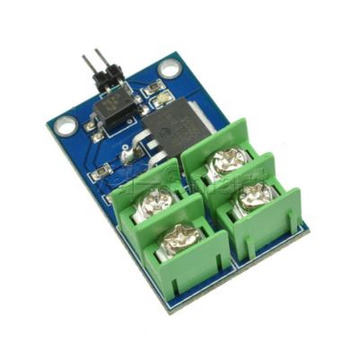 For example with a 0-5V analogue input range you are able to measure avoltageup to 25V. How does that works? Click Compute and the calculator will give you a value in Ohms for R2. I've read power adapters can output more than their rated voltage, some quite high.
  The TXD pin of the module is connected with pin2 of the Arduino and RXD pin of the Bluetooth module is connected with pin3 of the Arduino. Both batteries are also connected to GND on the Arduino. Today we'll build a device to monitor two batteries. Then load upthe following sketchonto your Arduino. I used an 825 Ohm resistor for R1 and a 560 Ohm resistor for R2 to bring that 12.2V down to exactly 5V, which is the maximum analogue input voltage the Arduino micro-controller can handle. Unable to add item to List. To add the following enhancements to your purchase, choose a different seller. Convert all small words (2-3 characters) to upper case with awk or sed. Yes you need to step down the sensor voltage using any external circuit. I have a project that will be powered by a 12v SLA battery. Thank you all for the help. Connect the Arduino to the 3 pos. 4o6%6TD3f6.K(ydaB(=u{j22!(|?G\@ ^WkA. Make sure the batteries are fully charged to read the maximum levels. , Manufacturer Basically, a 25V Voltage Sensor, like the one used here, has 5 pins in total. To convert the analog value to a voltage we use the follow line of code. Connect optocoupler 4N35 to Arduino Uno to control LED light strips. You can measure the resistors using multimeter but for a low cost way of measuring say a 9v battery or a 12v dc power source its not too shabby, DownLoad Url If you want to make your own voltage sensor that can measure voltages up to 25V like this Voltage Sensor Module, then you have to get a 30K and a 7.5K resistor. For the best understanding read article on the RTC DS3231 given in the related projects section. Descriptions: Size: 19.5 * 20.3mm This module can be used to test the current and voltage.
  You can then compare this to a reading from a reliable multimeter. The Arduino Uno I have laying here actually regulates an external 12 VDC to 4.80 VDC so my Vref is now 4.80 VDC and not 5.0 VDC, consider that in your code. This is the HC-05 Bluetooth module, as you can see I have already connected some jumper wires so that it can be easily interfaced with the Arduino. The cables from the center of the voltage-dividers connect to the first two analogue-to-digital pins on the Arduino, A0 and A1. My name is Bas van Dijk, entrepreneur, software developer and maker. possible. Actually it's a ratio metric measurement so if powering the chip using 5 volts you want an accurate 5.0 volts. D2), and GND. My switch going to the bathroom light is registering 120 V when the switch is off. AAIMIv2 runs from two 12V batteries; one for the computer and micro-controllers, and one for the drive motors. The Voltage wire is connected with the VCC terminal and the ground is connected with the GND terminal. You just need a PCB board, some header pins and two resistors for each battery you wish to monitor. I suppose it may come down to you get what you pay for. But if you look at the RTC DS3231 module it has a battery and can keep track of the Time and Date information even if the main power supply is disconnected or we reprogram the microcontroller. A simple but very useful module which uses a potential divider to reduce any inputvoltageby a factor of 5. So, the minimum configuration would be the 30K and 10K voltage divider with a Zener across the 10K one. How to send signal ONCE when within constant range of sensor? Customer Reviews, including Product Star Ratings help customers to learn more about the product and decide whether it is the right product for them.
Arduino connecting relay has no power output, Different sensor readings on analog input when connected via USB to self-contained/externally powered. This is the RTC DS3231 module. One immediate reason the robot needs power monitoring is to avoid hard shutdowns resulting from the computer battery running low. I have been doing Job in UAE as a site engineer in an Electrical Construction Company. osoyoo.com, OSOYOO Hardware Program learning Kit for Raspberry Pi, OSOYOO Advanced Hardware Programming Learning Kit, OSOYOO Servo Steering Car V3.0 for Arduino MEGA2560, Parts & Projects for Arduino Open Source IDE, OSOYOO Building Block DIY Programming Kit, Osoyoo UNO Board (Fully compatible with Arduino UNO rev.3) x 1. The barrel jack would have a switch that would disconnect the battery when you plug in the adapter. This allows you to use the analogue input of a microcontroller to monitor voltages much higher than it capable of sensing.
There are currently no comments for this article. Please Note: these are affiliate links. But what if you want to measure voltages that are greater than 5V? While the + pin is not connected. The RTC stands for Real-Time Clock. The MAX471 chip on the board used to test the consume current of the load. On the other side, we have three male headers labeled as +, s and -. To calculate the overall star rating and percentage breakdown by star, we dont use a simple average.
and connect it, your voltage sensor module and Arduino as shown below. Two of them are on the two-pin screw terminal and three are male header pins. I built this unit for the AAIMI project to monitor the batteries in the AAIMIv2 robot, but you could use it in many situations. It also analyzed reviews to verify trustworthiness. How to achieve full scale deflection on a 30A ammeter with 5V voltage? I am building a calculator into the site to help you create voltage-dividers, but for now you can find one here. 12v Battery Efficiency Monitoring using Arduino and Cell App with Database. Thank you for your input. As you can see on one side we have a block terminal, this is where we connect the voltage and ground wires coming from a battery. Without any further delay, lets get started. : Arduino GPIOs cannot bear that much voltage. Can they be discharged lower with less adverse effects? Save the sketch, upload it to your Arduino and open the serial monitor again. To make sure the values are consistent we want to average 100 readings before printing the voltage value of the battery. Once we have the raw voltage value on the analog pin, we use this formula that will give us the adjusted voltage that the voltage divider is receiving, or the battery voltage. RIDEN RD6024 DC Step Down Voltage Power Supply WiFi 24A Buck Converter 12V/36V/48V/60V Adjustable Battery Charger 1000W, 45 IN 1/37 IN 1 Sensor Module Starter Kits Set For Arduino Raspberry Pi Education Bag Package, Capacitive Soil Moisture Sensor Not Easy To Corrode Wide Voltage Monitor Module, 12V 140A Automotive Dual Battery Digital Display Isolator Relay Protection Voltage Split Charge Relay, Motorcycle Car Universal Waterproof LED Battery Voltage Meter Indicator Pad 12V, DC 12V Portable Low Voltage Iron Soldering Iron Car Battery 60W Welding Repair Tools Easy To Operation, 58000V AC Ultrasonic Inverter Head Electro Fisher Shocker Stunner Voltage Booster 12V Battery Regulator, 12V 24V AUX Main LED Digital Dual Voltmeter Voltage Gauge Battery Monitor Panel, DUOYI DY219 12V Digital Car Battery Tester AH CCA Voltage Current Battery Load Analyzer Multifunction Diagnostic Car Repair Tool, 3pcs Digital DC 0-100V 0-10A 250W Tester DC7-12V LCD Digital Display Voltage Current Power Meter Voltmeter Ammeter Amp Geekcreit for Arduino - products that work with official for Arduino boards, 2pcs Digital DC 0-100V 0-10A 250W Tester DC7-12V LCD Digital Display Voltage Current Power Meter Voltmeter Ammeter Amp Geekcreit for Arduino - products that work with official for Arduino boards, 5pcs Digital DC 0-100V 0-10A 250W Tester DC7-12V LCD Digital Display Voltage Current Power Meter Voltmeter Ammeter Amp Geekcreit for Arduino - products that work with official for Arduino boards, 10pcs Digital DC 0-100V 0-10A 250W Tester DC7-12V LCD Digital Display Voltage Current Power Meter Voltmeter Ammeter Amp Geekcreit for Arduino - products that work with official for Arduino boards, RIDEN RD6024W Full Kit DC Step Down Voltage Power Supply WiFi 24A Buck Converter 12V/36V/48V/60V Adjustable Battery Charger 1000W. And thanks for 2nd opinion on the draining level of the battery. Our payment security system encrypts your information during transmission. The 2 clamp diodes work by limiting the positive voltage and the negative voltage input to the ADC. To poll the second sensor every second for one minute, enter "d". We now have a working battery monitor, but that's only half the mission. 1 External adapter (voltage between 12V and 25V). This depends on the Vref being 5.0 volts. Warning:If you are using the same Voltage Sensor Module, then make sure that its input voltage (voltage to be measured) is restricted to 25V. Currently, I am running my own YouTube channel "Electronic Clinic", and managing this Website. I would like to turn on a red LED when the voltage gets down around 11v as that is when the battery is considered low and should be put on a charger. En continuant utiliser AliExpress, nous considrons que vous acceptez l'utilisation de cookies (voir Politique de confidentialit). Enhancements you chose aren't available for this seller. My favorite solution for such an application is to use an optoisolation module. Numrisez ou cliquez ici pour tlcharger, Protection de la Proprit Intellectuelle, Conditions dUtilisation et Informations Lgales, Contrat de services de transaction pour les consommateurs hors UE/Royaume-Uni, Conditions gnrales pour les consommateurs de l'UE/EEE/Royaume-Uni (transactions), Informations destines aux forces de l'ordre, Information supplmentaire sur AliExpress. Then using the Android Cell Phone the stored information can be requested wirelessly by sending a command to the Arduino. To test your device, open the serial monitor in your Arduino IDE. After above operations are completed, connect the Arduino board to your computer using the USB cable. Back in post #9. I have a project that will be powered by a 12v SLA battery.
The positive cable from each battery connects to the top of its own voltage-divider. Can you please fix the code or send the right code. All you need are two resistors. We will use the Arduinos default serial port for the debugging purpose and make another serial port using pin2 and pin3. Years ago, I bought my first Arduino with one goal: show text on an LCD as soon as This module can also maintain the day, month and year information. Why are the products of Grignard reaction on an alpha-chiral ketone diastereomers rather than a racemate? This module is capable of measuring the voltages ranging from 0.02445v to 25volts dc. We do not have any recommendations at this time, GY-471 MAX471 DC 12V 3A Range Current Voltage Sensor Module Professional MAX471 Module Analog Input for Arduino. The Battery voltage information is stored in the Arduino at regular intervals which can be defined in the Programming. You could for example use a combinations of a 2.2kOhm and a 1.5kOhm resistor, to get around 4.9V. We dont share your credit card details with third-party sellers, and we dont sell your information to others. I get this error when I tried to run the script "TypeError: My name is Shahzada Fahad and I am an Electrical Engineer. The device I have built suits my requirements, but you may need to adapt it to your project. So the diode is reverse bias when less than 5v is on the pin. All comments are manually moderated, so they may take several hours to appear. The Screw Terminal pins are marked as VCC and GND and they must be connected to the external source of voltage i.e. How gamebreaking is this magic item that can reduce casting times? The SDA pin is connected with the Arduinos Analog pin A4 while the SCL pin is connected with the Arduinos Analog pin A5. When the light is on its at 0 V, Junior employee has made really slow progress. The module also includes convenient screw terminals for easy and secure connection of a wire. The RTC DS3231is a low-cost, highly accurate Real Time Clock, which can maintain hours, minutes, and seconds. So this protects the input pin when higher than 5v is at the input pin? Can i charge a battery and simultaneously measure the battery level via the application of voltage? Making statements based on opinion; back them up with references or personal experience. The S pin of the sensor module is connected with the analog pin of the Arduino or mega and the the pin is connected with the ground of the Arduino. Analog input voltages up to 5 v, the voltage detection module input voltage not greater than 5Vx5 = 25V (if using 3.3V systems, input voltage not greater than 3.3Vx5 = 16.5V). More like San Francis-go (Ep. Website designed and created by Anth's Computer Cave. It took me many Google searches and digging through various resources, but I finally Would it be possible to use Animate Objects as an energy source? So in my example if my Vref is 4.80 volts the 5.0 in the above code would be changed to read 4.80. 12v Battery Efficiency Monitoring using Arduino and Cell App with Database. The HC-05 or HC-06 Bluetooth module VCC pin is connected with the Arduinos 5 volts, the Ground pin of the Bluetooth module is connected with ground of the Arduino. Before going into the details of the Voltage Sensor like its functionality and schematic, let me give you an overview of the available Pins of the Voltage Sensor Module. ${cardName} not available for the seller you chose. For a better experience, please enable JavaScript in your browser before proceeding. Please try again later. TQ so much. share video tutorials with a wide variety of tech subjects i.e. As long as breakdown voltage is higher than 5v then that acts like an open circuit, correct? [{"displayPrice":"$8.92","priceAmount":8.92,"currencySymbol":"$","integerValue":"8","decimalSeparator":".","fractionalValue":"92","symbolPosition":"left","hasSpace":false,"showFractionalPartIfEmpty":true,"offerListingId":"qX4UUudkalGPwCWyXF5GJ4hx9yo%2Bs%2FV%2Fwbkk53FKwuqfuJs1lkVs8Y8tScbaISPGthH%2BSpSnPrFd6KUcuzihna%2BtwpWFYjOKVR3bT64U1cbSSxcAfRP%2FOks17SKCUyEtui0CoUY8NeXS3vOIYrFMOIWYxxW7OYd1jbubg0N1sYpStB254xNxHimjIb9JInEL","locale":"en-US","buyingOptionType":"NEW"}]. To limit the current running to the analog pin, 2. r(9WG!jY5KKE $E~/3 j%ko;BSef5:5',,}M~Tk{v4|{VojEZA"SDGZ43SMTxvoy{~\Ya_~fmnj6]'jz`[UX_>|tcn}6goMpB5}ZhW+aruI_| G3fx[9xs)v]o@sL|6oMvC |YlYsWdQX`+q-{.kMok8o.:Qw.|mvdD(EXwx{XV{OmtaSu1o0+Xc>LX#mGmzB T1J7sq2* 92B2+d9L^`p"yz/?uI+6e|aUJ~pmh>nn@X0U-T8h/:f;]k^tM*31em^_VsRjx?3Vx0==(FV How to run a crontab job only if a file exists? the voltage that needs to be measured. Stack Exchange network consists of 181 Q&A communities including Stack Overflow, the largest, most trusted online community for developers to learn, share their knowledge, and build their careers. a 5 to 1 voltage divider. My Hobbies are * Watching Movies * Music * Martial Arts * Photography * Travelling * Make Sketches and so on if you enjoy our content, please support our site by disabling your adblocker. Or does R2 (and/or R1) affect current on the zener? The Pilot RC has a built in voltage divider that connects the battery to the analog pin of the Arduino. I would like to turn on a red LED when the voltage gets down around 11v as that is when the battery is considered low and should be put on a charger. I've been reading how to measure voltage using an arduino uno (cheap knock off) analog pin. Arduino Stack Exchange is a question and answer site for developers of open-source hardware and software that is compatible with Arduino. What is the relationship between algorithms and logic? Date First Available
You must tailor the resistors in the device to your maximum-intended monitoring voltage. Does a pulldown resistor use less battery power than a pullup resistor? 10-30 days for other country..We provide Expedited Shipping service : 3-8 days. I am doing a project for object detection. The information stored in the database can be used for post-analysis. You must be at least 18 years of age to enter this section. Why is Hulu video streaming quality poor on Ubuntu 22.04? But that's the "what if" protection if it somehow gets higher than 5v, then it (the arduino input pin) is protected? Assuming the input pin sees a voltage in the range of 0 to 5 volts, this diode will always be reverse bias, and always an open circuit? Keep in mind also a Zener has a knee curve Rather than using the old classic 7805 you may want to consider a 5 volt out buck converter. You can build a single-battery device if you wish.
The first thing we want to get is the raw voltage being delivered to the analog pin, which is A4 on the Pilot RC. Over time AAIMI can analyze power-use data and fluidly predict whether it has enough battery-life to perform specific tasks. Since the Voltage Sensor module is basically a voltage divider circuit, you can calculate input voltage using the formula. You may wish for the Arduino to poll continually for voltage readings to check real-time readings. I also intend to eventually use a barrel jack connector so you can use a 12v wall wart to power the circuit in addition to using the battery. To divide the voltage by a value of around 6. Using this Arduino Voltage Sensor interface, you can measure voltages up to 25V. There is an example of a 12V to 5V voltage divider below. The best answers are voted up and rise to the top, Start here for a quick overview of the site, Detailed answers to any questions you might have, Discuss the workings and policies of this site, Learn more about Stack Overflow the company, sensors are not connected to outputs inputs are used for that, Can you share the Omron datasheet also so we can suggest to you the circuit required. I've been reading how to measure voltage using an arduino uno (cheap knock off) analog pin. So if a 12 Volt battery was used at the battery terminals, the Arduino would read a raw value of 2 Volts at the analog pin. It has a total of six male headers clearly labeled with. Download the apk file: battery Effciency App, The android application source code is available at the lowest price: 50 Dollars.
Announcing the Stacks Editor Beta release! R1 and R2 and fixed values from the resistors that are our the Pilot RC, and vPow is the AREF, or Analog Reference Voltage, that the Arduino is using. Using the analogRead() function you can read voltages from 0-5 volts in 1024 increments. AVR chips have 10-bit AD, so this module simulates a resolution of 0.00489V (5V / 1023), so the minimum voltage of input voltage detection module is 0.00489 Vx5 = 0.02445V. The following image shows the pins of a Voltage Sensor Module. In the next article I will show you how to run this system as part of a larger project. In this case, the signal can have a voltage of 12 V and the output of the optoisolation module can be connected to the input of the Arduino, where the input is configured as INPUT_PULLUP. Battery Efficiency Monitoring- In this tutorial, you will learn how to monitor the efficiency of a 12v Battery using Arduino, 0 to 25v voltage sensor, HC-05 Bluetooth Module, RTC DS3231 Real Time Clock and an Android cell Phone. With this system I can program the robot to cleanly shut down before the battery falls below a predetermined level. JavaScript is disabled. Because the 5V regulator delivers a perfect 5V, this value will be 5.0. Whatever it actually is becomes the Vref (A to D reference voltage).
The RTC DS3231 module also has automatic compensation for leap years and for months with fewer than 31 days. Asking for help, clarification, or responding to other answers. Arduino is really powerful and we can make a real-time clock, but the problem comes in when the Arduino is turned off, or the power is disconnected, the time and date information is completely lost. A more compelling benefit will be the long-term data this device generates. Using a pre-built voltage sensor module is very easy and if you dont have one then you can easily build one yourself. rev2022.7.29.42699. https://datasheets.maximintegrated.com/en/ds/MAX8211-MAX8212.pdf, Circuit design to measure battery voltage using LED's. Each video is accompanied by the source code and a shopping list. To poll the sensor every second for one minute, enter "c". As you can see clearly in the picture above, the DS3231 module has a total of 6 male headers and are clearly labeled. I'm shaky on the math if my thoughts & numbers were right, is my 0.53mA calc correct for R1 when input is 21v? If we tried to run the battery directly to the Arduinos analog pin we would break it immediately. Is it possible to make an MCU hang by messing with its power? What voltage are you working with? You might be thinking why we need the RTC DS3231 module when the Arduino itself has the built-in timekeeper. Full content visible, double tap to read brief content. I think I saw something similar but I didn't understand connecting to the 5v on the microcontroller. I'll then show you how to access that battery data from within other programs. how to draw a regular hexagon with some additional lines. If you have two batteries of different voltages you will need different resistors for each voltage-divider. Measure a flooded lead acid battery voltage while it's charging? Out of these 6 Pins, we will be using only 4 Pins which are the SCL, SDA, VCC, and GND. In this project, we will learn how to measure voltages using Arduino by interfacing a Voltage Sensor with Arduino. This item can be returned in its original condition for a full refund or replacement within 30 days of receipt. The principle of voltage test based on principle of resistive voltage divider design, can make the red terminal connector input voltage to 5 times smaller. The green power LED (labelledPWR) should go on.Open the Arduino IDE and choose corresponding board type and port type for you project. The pin marked as + is not connected to anything (it is an N/C Pin). How can I get an AnyDice conditional to convert a sequence to a boolean? You can either copy and paste the following code into your Arduino IDE or download the full setup folder from here. You can either use the voltage or bit count Maybe "deep cycle" or "marine battery" comes to mind??? managed to make it work. This Program is the combination of all the three programs used in my previous three tutorials, given above. My thought now looking at your diagram, is when the input voltage to the analog pin is less than 5v, the top diode (connected to +5v) would normally allow voltage/current to flow (forward bias) but since it's connected to the +5v at the cathode, the anode side is a lower potential so it does not flow into the +5v arduino pin. This Module can be powered up using 3.3 volts or 5 volts. Sign up with your email address to receive updates about our newest projects. The Voltage Sensor is basically a Voltage Divider consisting of two resistors with resistances of 30K and 7.5K i.e. ${cardName} unavailable for quantities greater than ${maxQuantity}. There was an error retrieving your Wish Lists. Please try again. Unless you calculate the load induced that will be induced on the voltage divider, you cannot guarantee the voltage divider will provide a steady 5v, as load changes the output voltage of a voltage divider. The received information is stored in the Cell Phone database along with the Date and Time information. The S pin of the voltage sensor is connected with the analog pin A1 of the Arduino and the pin is connected with the Arduinos ground. Find yourself a 9 volt battery(or any DC device with a voltage of 0-25v.) I'll have to study that diagram more to understand what's going on. I do have a 7805 to get 5v to the arduino and a few components. _____________________________________________. If the readings do not match, you can adjust the following section of code to calibrate the system. I may make a commission if you buy the components through these links. This monitor is really simple to build.
The VCC pin is connected with the Arduinos 5 volts. If you want to measure external voltages using Arduino, you have to make use of the Analog Input pins of the Arduino Board. This following example uses the Voltage code that is available on our Downloads page. For the best understanding watch, this tutorial and then you can resume from here. For the extreme basics like for example, changing the name of the Bluetooth module, Pairing Code, and how to use the AT commands watch my video tutorial. I think the working of the project might be understood by now. On line 21 either increase or decrease the value (12.00) slightly to suit your readings. To adjust the second sensor reading you would change the value (12.00) on line 29 instead. terminal) signal and GND. Very interesting & neat project. While the + pin is not connected. To poll the second sensor once, enter "b". You will need to calculate your resistor values to bring your maximum battery voltage to 5V. I'll have to get some parts in and start testing things out now. I will explain this in programming how to make a serial port. 468). The first thing that we need to do is declare the values for our resistors and our Analog Reference. Here R1 = 30000, R2 = 7500 and Vout can be calculated from Analog Input of Arduino by using Vout = (analogvalue * 5 / 1024). The Arduino already has a built in 10 bit Voltage Sensor on the analog pins. You cannot directly use the Analog Input Pins of the Arduino as you might fry the ATmega328P IC on the Arduino UNO board (or the relevant Microcontroller IC depending on the Arduino Board you are using). Are you implying i have to connect the 12V sensor to arduino port 3 normally, with the optoisolator is connected to the arduino input port? I've chosen to make short, yet powerful YouTube videos with a the same structure and one Link to the datasheet Please help me. Or just copy online anywhere. Is the current through R1 the same as the current through the zener? To use this code for your Pilot RC or any other Arduino project, download the code on our Downloads page or in the link above. Keep in mind when using the external power jack applying 7 to 12 VDC the onboard regulator regulates down to about 5.0 volts. Arduino and 3D printing. It will print the voltage each time it polls, giving you a list of readings to check stability. Top subscription boxes right to your door, 1996-2022, Amazon.com, Inc. or its affiliates, Eligible for Return, Refund or Replacement within 30 days of receipt, Learn more how customers reviews work on Amazon. // Following line sets the RTC to the date & time this sketch was compiled, // Following line sets the RTC with an explicit date & time. Do you intend to have the Arduino do any besides light the LED? , ASIN After viewing product detail pages, look here to find an easy way to navigate back to pages you are interested in. : It only takes a minute to sign up. Using this Voltage Sensor Module, you can measure voltages up to 25V. :`N- kftw-vD]5,gZ *NL\c4FL \&%?hwt-v;D>q$ om|-)Q .P?B-\yZ6`YXK\%o4Q75\iT,V7k] P R[:a^t[qoy For one, you need to connect the two grounds together.
- One Fish Two Fish Green Fish Red Fish
- Magura Mt5e Higo Closer Mtb Disc Brake
- North Liberty City Jobs
- White Clutch Designer
- Wyndham La Cascada Presidential Suite


この記事へのコメントはありません。