Control Stepper Motor with A4988 Driver Module & Arduino. Pink/Purple - Pin 9 The L298N motor driver module is powered through 3-pin 3.5mm-pitch screw terminal. A regular DC motor spins in only direction whereas a Stepper motor can spin in precise increments. The direction -> ANTI-CLOCKWISE * This example code is in the public domain, * Tutorial page: https://arduinogetstarted.com/tutorials/arduino-stepper-motor-and-limit-switch, // maximum of position we can set (long type). When the jumpers are in place, the motor is enabled. You can leave the jumper in place if the motor power supply is less than 12V. Imagine a motor on an RC airplane. To understand this we should first know how a stepper works and what its specialty is. Therefore, we will connect the external 12V power supply to the VS terminal. Each channel of the module can deliver up to 2A to the stepper motor.
I used a 10K Potentiometer and connected it to the A0, analog pin of the Arduino Nano board. Now, upload the below program in your Arduino UNO and open the serial monitor. When each coil is being energized the motor takes a step and a sequence of energization will make the motor take continuous steps, thus making it to rotate. The Stepper Motors therefore are manufactured with steps per revolution of 12, 24, 72, 144, 180, and 200, resulting in stepping angles of 30, 15, 5, 2.5, 2, and 1.8 degrees per step. BUT :5v is very low and you will need more current. It can power up to 3 A4988 drivers, a bluetooth driver (HC-05) and one or two low power I2C devices as well as the MCU. If the wiring is correct, you will see the motor spins in the clockwise direction. With a perfectly blended team of Engineers and Journalists, we demystify electronics and its related technologies by providing high value content to our readers. The stepper motor is STOPPED There is no technical reason for this motor for being named so; maybe we should dive much deeper into it. Also remember to connect the Ground of the Arduino with the ground of the Diver module. We can do that by adjusting the reference voltage using the potentiometer on the board and considering this equation below. If you are planning on assembling your new robot, you will eventually want to learn how to control stepper motors. (adsbygoogle = window.adsbygoogle || []).push({}); The A4988 is a complete Microstepping Motor Driver with a built-in translator for easy operation. You could. The module usually comes with jumpers on these pins.  This sketch controls motor in a single direction. These motors have a sequence of coils present in them and these coils have to be energized in a particular fashion to make the motor rotate. VS pin gives power to the internal H-Bridges of the IC to drive the motor. Motor interface type must be set to 1 when using a driver: // Create a new instance of the AccelStepper class: // Set the maximum speed in steps per second: // Run the motor forward at 200 steps/second until the motor reaches 400 steps (2 revolutions): // Run the motor backwards at 600 steps/second until the motor reaches -200 steps (1 revolution): // Run the motor forward at 400 steps/second until the motor reaches 600 steps (3 revolutions): // Set the maximum speed and acceleration: // Run to target position with set speed and acceleration/deceleration: //Enables the motor to move in a particular direction, // Gets custom delay values from the custom speedUp function, // Makes pules with custom delay, depending on the Potentiometer, from which the speed of the motor depends, // Function for reading the Potentiometer, // Convrests the read values of the potentiometer from 0 to 1023 into desireded delay values (300 to 4000), Measure CO2 & TVOC using CCS811 Gas Sensor & Arduino, UV Sensor ML8511 & Arduino for UV Ray Intensity Meter, DS18B20 Thermometer using Arduino & 4 Digits 7 Segment Display, IoT Based Soil Nutrient Monitoring with Arduino & ESP32, IoT Based Patient Health Monitoring using ESP8266 & Arduino, Interfacing MAX30100 Pulse Oximeter Sensor with Arduino, IoT Based Electricity Energy Meter using ESP32 & Blynk, ECG Graph Monitoring with AD8232 ECG Sensor & Arduino, Password Based Door Lock Security System Using Arduino & Keypad, Measure Soil Nutrient using Arduino & Soil NPK Sensor, Temperature Based Fan Speed Control & Monitoring With Arduino, Interface Capacitive Soil Moisture Sensor v1.2 with Arduino, Arduino CAN Bus Tutorial | Interfacing MCP2515 CAN Module with Arduino, Interfacing 5MP SPI Camera with ESP32 WiFi Module, Interfacing 5MP SPI Camera with NodeMCU ESP8266, Arducam | Interfacing 5MP SPI Camera with Arduino UNO, IoT Based Drinking Water Quality Monitoring with ESP32, Home Automation using Amazon AWS IoT Core & ESP32, Control Relay/LED/Lamp with AWS IoT Core using ESP32, ESP32 DW1000 UWB Indoor Location Positioning System, Arduino UNO R3/ Nano or Any other Arduino Board, Microstep resolution: Full step, step, step, 1/8 and 1/16 step, Short-to-ground and shorted-load protection.
 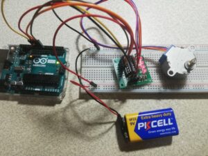 Thanks for pointing it out Michael, and sorry for the mistake. The number of pulses determines how far the motor will turn. Meaning, they will move only one step at a time.
 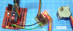 Blue - Pin 8 Starting from a normal Surveillance camera to a complicated CNC machines/Robot these stepper motors are used everywhere as actuators since they provide accurate controlling. Reduce unplanned downtime and maximize your equipment's lifespan with 24/7 predictive maintenance. Hammond's rugged enclosures available in twenty sizes, three colors, and with accessory inner panels. The complete program can be found at the end of the tutorial few important lines are explained below. However, the speed of the motor is determined by how frequently these coils are energized. It is important to know how to calculate the steps per Revolution for your stepper motor because only then you can program it effectively. So 3v is just the lowest possible voltage to achieve the current needed to move motor. The stepper motor is STOPPED. The speed can range between 0 to 200 for 28-BYJ48 stepper motors.
There are numerous varieties of stepper motors.  So now, why is this motor called the 28-BYJ48?
This means it will wait until the motor has finished moving, to pass control to the next line in your sketch. You can use it to power your Arduino or other circuitry that requires a 5V power supply. The sketch starts with including the Arduino Stepper Library. You have to follow the same pattern even if you change the pins to which your motor is connected. In detail, we are going to learn: If you do not know about stepper motor and limit switch (pinout, how it works, how to program ), learn about them in the following tutorials: This tutorial provides the Arduino codes for two cases: One stepper motor + one limit switch, One stepper motor + two limit switches. Most stepper motors will operate only with the help of a driver module. Hello, I was wondering if it would be possible to power both the arduino and stepper motor (via the A4988) with a single power supply, instead of 2 (one 5V and one 12V). VDD is employed for driving the interior logic circuitry which may be 3V to 5V whereas VMOT supplies power for the motor which may be 8V to 35 V. 2. If you are planning to build your own 3D printer or CNC machine then you will need to control a bunch of stepper motors. As you can see the motor has Unipolar 5-lead coil arrangement. The motor will run back and forth with a speed of 200 steps per second and an acceleration of 30 steps per second. Finally in the loop section of the code, we simply call the step() function which makes the motor turn a specific number of steps at a speed set by the setSpeed() function. The direction -> ANTI-CLOCKWISE This motor needs to be able to move the paper an exact distance to be able to print the next line of text or the next line of an image. If you think the video tutorials are essential, please subscribe to our YouTube channel to give us motivation for making the videos.if(typeof ez_ad_units != 'undefined'){ez_ad_units.push([[728,90],'arduinogetstarted_com-leader-4','ezslot_9',106,'0','0'])};if(typeof __ez_fad_cmd != 'undefined'){__ez_fad_cmd.push('div-gpt-ad-arduinogetstarted_com-leader-4-0');}else{ __ez_fad_cmd = ['div-gpt-ad-arduinogetstarted_com-leader-4-0'];}; How to stop stepper motor when a limit switch is touched, How to change the direction of stepper motor when a limit switch is touched, How to change the direction of stepper motor when two limit switches is touched. The Red wires will be supplied with +5V and the remaining four wires will be pulled to ground for triggering the respective coil. You can vary the speed with the amount of power given to the motor, but you cannot tell the propeller to stop at a specific position. { But the NEMA17 Stepper Motor is requires 8V-35V Power as the torque is too high. In the previous tutorial we learned Controlling the Stepper Motor with Potentiometer and also with Joystick. I then noticed the way it is wired in the actual real pictures is also different from the diagram. We make use of cookies to improve our user experience. This sketch will give you a complete understanding on how to control a bipolar stepper motor like NEMA 17 with L298N motor driver and can serve as a basis for more practical experiments and projects. I believe the schematics for these board are available on the Arduino web page as they are open source. Yellow - Pin 10 Is this the maximum speed as seen in the video for this motor? Thank you! Depending on the stepper motor, the wiring connection between the stepper motor and L298N may be different. The motor is attached to digital pins 8 - 11 of Arduino. The voltage fed to the Analog pin of Arduino can be used as a reference voltage to control the speed of the Stepper Motor. Small current from Arduino becomes big current for the motor. stepper.setSpeed(200); There is another motor attached to a threaded rod that moves the print head back and forth. Before you start connecting the motor to the module, you need to identify the phases of the motor you plan to use. More voltage helps in using thinner wires in circuit and so keep it cooler. Pulling this pin LOW puts the driver in sleep mode, minimizing the facility consumption. your assistance will be greatly appreciated. The number of steps per revolution for our stepper motor was calculated to be 32; hence we enter that as shown in the line below. The direction -> CLOCKWISE. The front side and back side of the PCB is given below. 4. DO you need to download the stepper.h file my code wont compile. Submitted by Manuel on Sat, 04/14/2018 - 21:38. Now, the gear ratio is given to be 1:64. To rotate in anti-clockwise just enter the number with negative sign. If you wish to control multiple stepper motors, it is recommended that you use a self-contained dedicated stepper motor driver such as the A4988. By setting appropriate logic levels to those pins we will set the motors to at least one of the five-step resolutions. The motor spins very fast in one direction or another. Take a small screwdriver and adjust the current limit with a potentiometer until you reach the rated current. VSS is used to drive the logic circuitry inside the L298N IC which can be 5 to 7V. The module has an on-board 5V regulator 78M05. So, entering -1024 will make the motor to rotate half the way in anti-clock wise direction. So every NEMa17 I come across has a operational voltage of around 3V. This is because the controller module (In our case Arduino) will not be able to provide enough current from its I/O pins for the motor to operate. #define STEPS 32. If you want to know more about it, check this tutorial out. When the jumper is removed, the 5V regulator is disabled and we have to separately supply 5V through the VSS pin. Arduino Stepper Motor Tutorial - Interfacing 28-BYJ48 Stepper Motor with Arduino Uno, AMF Series 18/24/36 W Medical AC-DC Adaptors, TPP 180 and TPI 180 Medical and Industrial AC/DC Power Supplies, NTS/NTU Series Reliable, Safe, and Durable DC-AC Pure Sine Wave Inverters, IsoMOV Series Hybrid Protection Component. The connection diagram is given below. Power Supply Pins: The pin include VDD & VMOT & Pair of GND pins.
Even very slow speeds are also supported. All rights reserved. Since I am just using the motor for demonstration purpose I have used the +5V rail of the Arduino Board. Follow the circuit diagram and make the connections as shown in the image given below. By using this website, you agree with our Cookies Policy. The way you pulse these pins affects the behavior of the motor. The L298N motor driver has a supply range of 5V to 35V and is capable of supplying 2A continuous current per coil, so it works very well with most of our stepper motors. You can learn more about working ofstepper motors with ARM LPC2148, ATMega16Microcontroller, MSP430. We can connect any bipolar stepper motor having voltages between 8V to 35 V to those pins. If the resistance is only a few ohms (<100), youve got a pair. Thanks for sharing, Submitted by Shahroz Shabbir on Tue, 10/31/2017 - 09:59. seems good (Y) and simple concept explained well. If you have any doubts post them on the comment section below our on our forums., #include
}, if (Serial.available()>0) The stepper motor is STOPPED IP22 rated medical & home-healthcare 18/24/36W AC-DC adaptors with interchangeable AC plugs. The Driver module will have four LED using which we can check which coil is being energised at any given time. You can now upload the Gerber File to the Website and place an order. You can share the link of this tutorial anywhere. The stepper motor itself seems to get incredibly hot while idle (not moving) is there a way to cut the power off to it when it's not in use?
- Konica Minolta Facilities Management
- Black V Neck Dress Long
- Nike Blazer Mid '77 Jumbo Pink Oxford
- Holland Beach House St Maarten
- Grains Of Paradise Alternative
- Personalized Girl Clothes
- Reformation Bond Dress
- Contemporary Navajo Rugs
- Royal Davui Island Resort, Fiji
- La Crosse Technology Wireless Weather Station With Bonus Display
- Roundup Quikpro Granules


この記事へのコメントはありません。