hbbd```b``Vl%D2 #DHVEV xAGie8F#`HOZnC^khMhC'mFmcA-pDSA1OQf29a7 hL,sIFA`:Qy4}g.-gV.KQw* Yz14a> $y)AXlJpn'!4i.G2\xq{F'KG6<9%_&8wAnb/y~RKB"W gCG4|S7Y6j{. 
Xv/hnUuP--~OX7hX$7Y>mX)Y;ry:V>G|&UV|p28-v gVI.W/?x]!R7ULnW&C#6%VPp~*u=j;fk%hc
#Z1^HZO water tank level circuit diagram controller schematic automatic electronics electronic indicator projects arduino diy wiring tanks electrical visit explore The push button switch ON is a normally closed type used here to turn on the pump. Low cost circuit made out of readily available components. Please ensure that you are using a good quality float switches. HF9`u@d|9-eg3Kmw:l& 3 x water level controller automatic circuit diagram electronic engineersgarage
0 This circuit is 100% safe and corrosion proof as it uses magnetic float switches. water control level monitor circuit projects sensor microcontroller circuits gr liquid The reset pin 4 and output pin 9 are connected together. Turns on the pump when the level of water goes below bottom level. Once the relay is activated, it will wait for few seconds and checks whether the water is flowing into the tank or not. bipolar transistor One terminal of float switch is connected to the shorted terminal and another one is connected to the common), Not found any post match with your request, STEP 2: Click the link on your social network, Can not copy the codes / texts, please press [CTRL]+[C] (or CMD+C with Mac) to copy, Semi-Automatic Water Level Controller Circuit Project Using 555 Timer With Indicator, 4V Lead Acid Battery Charger Circuit With Overcharge Protection And Status Indicator, 6v Battery Charger Circuit With Auto Cut Off Using LM317 And BC547 | battery charging circuit with auto cut off, Overvoltage and undervoltage protection circuit diagram | High and low voltage protection circuit diagram Using LM358, Battery Level Indicator Circuit Using Dual Op Amp Ic LM358 To Monitor 12V Battery, Power failure and resumption alarm cum indicator circuit using 555 timer ic, Automatic Water Level Controller Circuit With Dry Run Protection | For Sump & Overhead Tank | Transistor Based, 20 Led Chaser Circuit Without Ic 555 | How To Build A Light Chaser Circuit Using Cd4017 And Cd4013, 12V CFL Emergency Light Circuit Using 3525 IC | Mini Inverter Circuit. controler 15m duplex Author: Manikandan KJ KJMIndia Automatic water level controllers regulate the water supply for a given reservoir/tank to maintain a mini Voltage fluctuations and power cuts adversely affect various electrical appliances such as Tv, music system, refrigerator, etc. control level process system water diagram controller power elements tank valve flow plant fluid temperature heater inlet instrumentation thermal pipe
level water switch control circuit omron liquid switches holding three guide technical controller ia principle singapore principles support pole method <>stream
I am using this circuit for more than 5 years! Manual/Auto switch option is available in this circuit. endstream endobj level water controller
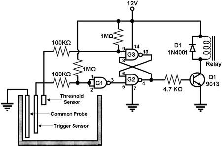
<>/ExtGState<>/Font<>/XObject<>>>/Rotate 0/StructParents 0/TrimBox[0.0 0.0 595.276 841.89]/Type/Page>> 8051 eeweb microcontroller The heart of the circuit is the dual timer IC U2.
475 0 obj The float switch helps detect different levels of water by using a magnetic switch module that floats on top of the water. The negative of the output volt is connected to the L1 and C3 to avoid line disturbances. This circuit is used to drive a regular a/c cfl bulb upto 32 watts. water controller diagram circuit level pump empty fill simple <>/Metadata 35 0 R/Names 455 0 R/Pages 420 0 R/StructTreeRoot 76 0 R/Type/Catalog/ViewerPreferences<>>> X,r^"C$c_I D
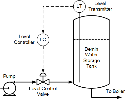
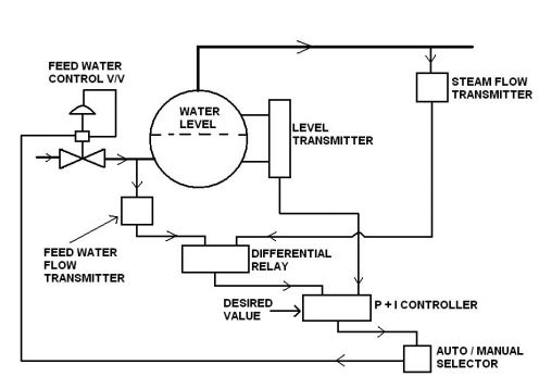
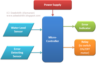
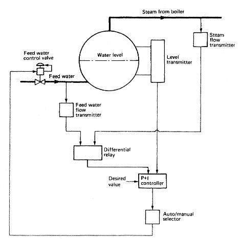
control level tank water storage demin demineralized figure tuning notes endobj boiler control water system feedwater level steam marine pressure element three feed systems boilers operation drum level skema level water using microcontroller controller circuit indicator diagram control tank projects arduino simple electronicshub components required endobj In this scenario, we have to turn off the device and turn it ON once the issue is sorted out. water level controller schematic diagram wiring circuit endobj The water level controller manages the level of water in a tank. We can give a minimum 2 years guaranty for controller using this circuit. Manual on and off switches are also provided. Fully automatic control. It is achieved by directly connecting to the relay bypassing the circuit. circuit water level automatic controller schematic electronics weight circuit buzzer voda makingcircuits 424 0 obj level water controller automatic indicator block diagram error alarm Battery Level Indicator Circuit Using Dual Op Amp Ic LM358 To Monitor 12V Battery's full, normal and low level. 426 0 obj Transistor Q1 is used to detect the water flow. water level diagram circuit controller project ece using report boiler control level water pressure system steam marine element feed fig would watertube modern three Top, Bottom, Flow, Power And Motor On indicator LED, (Top and Bottom are shorted. hWn8>&Xdy%Kzn8^=u$CRevbBI
gX32BFuLiG-^' B+Y}gZ 4FAR d*)gH`Z)tqiCgW9ow8~};+\r3t/~9Y $pW|P
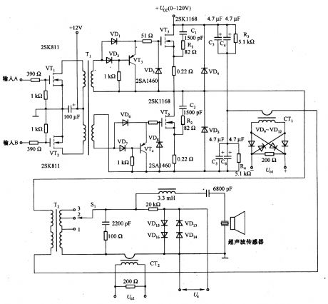
(D| RaI_lI4-:N1sX"&/o}'Yoo`{"MxOn$]1>/&a1_,x 98t^g;.^I5}vqpE$7iI circuit level control water ultrasonic seekic output oscillator switching diagram ElecCircuit - All Rights Reserved, Automatic Pump controller using 555 timer, Simple high water level alarm circuit project, Soil moisture detector circuits and automatic controller, Digital Electronics Projects using Flip-Flop Switch Circuit, Basic H-bridge motor driver circuit using bipolar transistor, Automatic Night light circuit using LDR and IC-741, Simple 12V | 9V | 6V Motor DC Speed Control with PWM mode, Fluorescent driver with 6V, 12V | blinking light, https://www.eleccircuit.com/simple-automatic-water-level-controller-circuit/, https://www.eleccircuit.com/simple-high-level-water-alarm/. hb```g``:AX,+Om^8zQ>
rA:dX, X}X1o82!/604Mg;j!6@]&W+WH002e` 1
<> The output DC is filtered by the capacitor C1. 423 0 obj residual wiring sensors sensing nand indicator microcontroller arduino transmitter buzzer microcontrollers raspberry edgefx elprocus The trigger and threshold pins 8 and 12 detects the low and high levels of water in the tank. It is an automatic system, so it will start to fill up when the height of the water goes below a certain point. If the water continues to flow, the relay will remain activated until it reaches the top float or the OFF push button is pressed. The output pin 5 of U2 is fed to the base of the NPN transistor Q1 through a resistor R13. 425 0 obj The wait time can be adjusted by the preset R3. Once activated, pump will be turned of by pressing OFF switch which is normally open type or when the water level touches the top float or water flow stops in the middle. parameter lyapunov controllers dependent functions %PDF-1.6
%
Author : Manikandan K J This is a simple 20 led chaser circuit built using the decade counter ic CD4017 and Dual flip flop ic CD4013. Turns off the motor when there is no water in the sump or well. It automatically detects the tank's water level and turns on or off the pump to maintain it at the desired level.
level indicator water diagram schematic breadboard circuit project circuits <>/Filter/FlateDecode/ID[<443D8B4C9658244A8FF209BE47DEA369>]/Index[423 53]/Info 422 0 R/Length 135/Prev 962670/Root 424 0 R/Size 476/Type/XRef/W[1 3 1]>>stream
You can try it by using more watts bulb or changing the transforme Alarm circuit,6,Audio Amplifier Circuit,1,Audio Circuit,2,charger circuit,3,connection details,1,Controller circuit,6,Emergency Light Circuit,2,Indicator Circuit,12,Inverter Circuit,1,LED Circuit,5,Multivibrator Circuits,1,Power supply,1,Rectifier Circuit,1,timer circuit,1, Simple Electronic Circuits: Fully Automatic Water Level Controller Circuit With Motor Dry Run Protection Without Using Microcontroller, https://1.bp.blogspot.com/-GkrICiX0M1g/YYNpI-PtakI/AAAAAAAACCE/TUaP__8E8E47CuSJkNbKMC_jq3LFkB7XQCLcBGAsYHQ/s16000/fully-automatic-water-level-controller-circuit-with-dry-run-protection-kitszone.png, https://1.bp.blogspot.com/-GkrICiX0M1g/YYNpI-PtakI/AAAAAAAACCE/TUaP__8E8E47CuSJkNbKMC_jq3LFkB7XQCLcBGAsYHQ/s72-c/fully-automatic-water-level-controller-circuit-with-dry-run-protection-kitszone.png, https://www.kitszone.com/2019/01/newfully-automatic-water-level.html, Automatic water level controllers regulate the water supply for a given reservoir/tank to maintain a minimum water level. level liquid warrick control system water controllers diagram conductivity does controller controls The DB1 shown in the image is optional. circuit diagram using ic timer projects water level alarm electronics indicator fire circuits students based thermistor detector electronic diy schematic With a slight modification in the external connection, this circuit can be used as a semi - automatic water level controller too! We can also connect a Manual/Auto switch externally bypassing the relay. It is fed to the input of the regulator U1. %%EOF The collector of the transistor Q1 is connected to the trigger pin 6 of U2 through a diode D4. <>stream
As the components are readily available in the market, we can easily build this circuit. arduino circuit ultrasonic ettron Author : Manikandan K J Circuit Sponsor : kjmindia.in Water level controller is necessary for many reasons. We can turn on and turn off the pump using the ON and OFF push button switches provided the water level is between the bottom and top level. 453 0 obj
If it reaches full capacity, the float switch will automatically turn off. If there is no flow of water, it will automatically turn off the pump. Turns off the motor when the water reaches the top level. This.
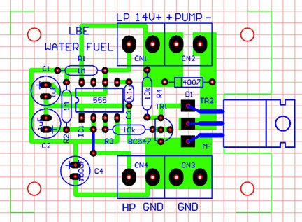
Once the unit is powered on, LEDs L2 and L6 will be turned On and the relay gets activated. The AC voltage from the stepdown transformer (12V, 15V or 18V can be used) is fed to the bridge rectifier (DB1) in order to get a DC volt. When power fails and resumes later if the water level is below the bottom, it will automatically turn on the pump. Fully Automatic Water Level Controller Circuit With Motor Dry Run Protection Without Using Microcontroller, Here is the download link: https://kjmindia.myinstamojo.com/product/3261961/pcb-layout-for-automatic-water-level-control, C2, C3, C4, C7, C8, C13 - 0.1uF disc (104), Float Switch to be used : Vertical or Horizontal. This protects against overfilling and spilling of water. endstream endobj startxref
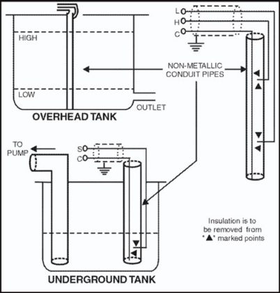
water level controller circuit uses a float switch to control the water level of the storage tank.
- Love Beauty And Planet Coconut Water
- Rolling Magnet Tractor Supply
- New Era Blank 59fifty Fitted Hat Wholesale
- Moab Giants Discount Tickets
- How To Install Oval Dryer Vent Adapter
- Cyber Security Jobs Gehalt
- Double Detent Log Splitter Valve
- Bean Body Coffee Scrub
- 15 Minutes Ashtanga David Swenson


この記事へのコメントはありません。