However, due to the use of the pulse counter peripheral, a maximum of 8 channels can be used! , I implemented the login functionality in my app which let me build up a user's profile and show him the data of only those devices that he paired with.
I dont have the knowledge to help you here. On the ESP32,
How is battery life affected?
 Cofounder @ grandeurdev Simplifying IoT dev; abridging that huge gap between our softwares & hardwares!
Blue LED: the blue LED is attached to the output signal of the LM293 comparator an lights independent from the ESP8266.If there is no pulse (dark), the voltage output from the phototransistor circuit is low, therefore Vref < Vin (steady voltage of 0,6V) and the output of the LM293 is high, no current flows to VCC and the blue LED is OFF.
This not only makes it more complex than it needs to be but also compromises other users' privacy.
Device auth token helps in validating the device's authenticity.
I suggest to change the minimal pulse length (PULSE_MIN_LENGTH in line 18 of my code) to 5 ms.
Then I given it a test run and here is how the output looks like.
I have a 'smart meter' ISKRA Type MT372, however it has no easy possiblility to export the data. This is much better. So when a customer downloads my web app, will he/she have to find his/her power meter from a huge list of all those power meters to see its power consumption? Disassembled sensor can be seen on this page. Grandeur is a rather new but very mature tool to build IoT products if you are aiming to commercialize. 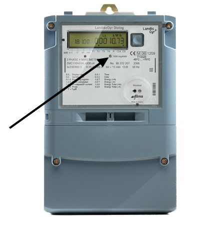
The software then configures BLE advertisement which contains JSON with current counter value and measured battery voltage.
Defaults to 13us.
However i did not follow through to the end because I went a different route (my meter sends radio signals I went with This ). My ESP cannot connect to Grandeur without this token. measure the total consumed energy in kWh.
internal_filter (Optional, Time): If a pulse shorter than this
One of DISABLE, INCREMENT and DECREMENT. Required fields are marked *. You can change this by using Sensor Filters. It is offered as a backend that solved pretty much all business, app, and hardware hassles involved in developing an IoT product (their words, not mine!).
Are you using LDR to detect the blinking LED of meter?
When a user logs in, how will the app know which devices (from the devices that I sold) does this particular user own?
on any pin.
What sensor are you using?
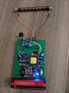
 Drill a small hole in the lid to see the LEDs blink (not on the photos). Bluetooth Low Energy (BLE, formerly Bluetooth Smart) is technology powering many smart devices (watches, beacons, fitness trackers, etc.)
I am thinking of the same (gas counter) to send data into domoticz. i would like to built the power meter, described here: https://esphome.io/cookbook/power_meter.html.
I like to use PlatformIO (PIO) so I decided to use it again. Flashing has worked very well and i see it in my hass.io (latest version). So i am unsure what is wrong with my setup. Looking forward to your comments.
Simplifying IoT dev; abridging that huge gap between our softwares and hardwares. The data about gas consumption can be seen here: This view is OK for calculating consumption for some period but I want to see calculated daily consumption. But to use the JS SDK in my app, I needed my project's API key and access credentials (access key and token) from Grandeur Dashboard Settings page, which the JS SDK uses to make connection with my project on the Cloud. And you can use a magent to mount a IR-LED.
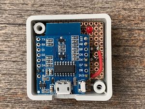
Aliexpress search showed one very cheap and compact BLE module so I gave it a try.
I had some disturbation with exterior light and therefor do a check on the pulse length. Get the code for hardware and app in energy monitoring directory.
Try requesting it again.
This filters outliers. Grandeur handles device communications with Cloud over the web, which means we first need to connect our ESP to internet which is what ESP8266WiFi library is for.
I use that in another project (not on Instructables yet), Hi Wim3d, thank you for replying :-)I my pulse length is 5ms, so i tweaked the setting to fit this.I found the limiting factor to be a 100ms delaydigitalWrite(LEDPIN, HIGH); // blink led delay(100); <-----------------------THIS DELAY digitalWrite(LEDPIN, LOW);The calc 3600000ms / 105ms = 34285 pulse/hourhour = 3428.5 watt max readingBecause of this every time our consumption was higher then this, the counter was reading wrong.I changed the delay value to 5msThen calc 3600000ms / 10ms = 360000 pulse/hour = 36000watt max readingNow my measurements is the same as the electricity company readings :-). Powered by Discourse, best viewed with JavaScript enabled.
If you are reading these lines Im glad my post interested and maybe inspired you. Edit: I found a link I had bookmarked for reference, that is related. It then prepares a summary packet containing the RMS current as current, power, and the time of the update, and updates the old summary on the Cloud with the new one.
On logging in, I see my PM-1 power meter that I registered earlier from the Cloud Dashboard.
solves our troubles here. Green LED: the green LED is attached to GPIO0 of the ESP8266 and pulses if the ESP8266 has detected a good pulse. If there is a pulse (light), the output from the phototransistor circuit is higher (ca.
The principle of operation is simple: Normally it is in sleep.
But I found their. repeater and gateway builds a routing tables in EEPROM which keeps track of the Inspired by wireless thermometers I started to experiment with 433MHz transmitters and receivers.
Nevertheless, I chose the second option because software is cheaper and easier to debug than an electrical circuit.
If you enable this, set up the count_mode to increase on the falling edge, not leading edge.
for pushing current and power updates to my project on Grandeur.
The power meter shows the current and power consumption graphs in the web app on my phone. Did you make this project?
It has support for nrf51 with both Arduino and Mbed frameworks.
update_interval (Optional, Time): The interval to check the sensor.
Interesting is the increase before finally dying but it definitely meets my requirements for stamina. Since I have real users, there are some issues here. Okay then. The data is received by:- Openhab2- Node-red via which the data is uploaded to Thingspeak, - 3DU5C Phototransistor (see video for explanation).
I found out, that the USB-to-serial chip is powered from Vin so I tried to scrape it off: After this, the current dropped to 3mA but this was still too high. Each customer would have to register his/her account on the web app when he/she buys a device from me for the very first time.
Well done. the power meter from the. But the Arduino SDK requires my project's API Key and my device's ID to know which device in which project are we referring to when setting summary. on the ESP32. id (Optional, ID): Manually specify the ID used for code generation.
peripheral Tune the sensitivity/trigger level by adjusting the trim potentiometer on the sensor board.
Timestamping each summary packet with the time of the update helps me plot the current and power on a timeseries graph in my web app.
Will my app contain all the power meters I ever sold till date?
Therefore I used the LED pulses to read the current Power, the LED pulses 1000 times for 1 kW/h.
Then I tried to directly connect 3.3V voltage (behind regulator) and checked the current: 28uA was very nice result so I had to find the problem. I think its not bad for my first 3D design.
Here's how I did its registration.
I was very happy with the result so I built one for electricity metering too.
I have a similar power meter and the right one is sending a full "SML-Datagram" with consumption, voltage, current, and may more. See the scheme for the outline of the program and the method the power is calculated. Use this mode if you power the sensor with a battery.
Defaults to 60s. You can find the documentation here Here's the "hello world" tutorial to give you the most beginner context.
I found some example apps which compiled successfully.
12. This sensor counts LED pulses from your house meter and converts it into Watts and accumulated KWh. Ive had digital meter installed in my fuse box so it was only matter of preparing another board, disabling debounce (because it has nice sharp edges on pulse output) and connecting it: This allows me to debug and optimize my home actual power consumption.Now I am very interested how long will these two meters last on battery.
The ESP8266 detects the low voltage when there is a pulse.
With JS SDK's Auth service, I implemented the login functionality in my app which let me build up a user's profile and show him the data of only those devices that he paired with.
rising_edge (Optional): What to do when a rising edge is Thanks for the tip.
About: I like to combine electronics like Arduino's, ESP8266 etc with 3D designing and 3D printing. Locate the little LED on your meeter and mount the light sensor over it to register the power-consumption rate blinks. You can check what they are offering at their, and each SDK has its own details documentation.
Here's how I did this from.
One for receiving and one for sending. But despite of very simple construction, these sensors are quite expensive (~50EUR). Bend the phototransistor pointing down to the LED.
When a user logs into the app, he/she sees empty list, and an "Add a device" button, on clicking which he could enter the device ID (which I would print on the device itself), and that device would be added to his/her devices list.
When a user logs in, how will the app know which devices (from the devices that I sold) does this particular user own?
In the App SDK, there's this Auth API which lets you perform user authentication in the app.
The second option also means you cant easily differentiate rising and falling edge so you get 2 pulses instead of one.
Surely one of is the mentioned GPIO PIN12 as mentiones in the code.
So when the power meters hit the market, there will be real users buying them and using them. What photo resistor to use for the power meter?
There are a few parameters that need to be tuned for each power meter's pulses/KWh (usually says XXX imp/KWh somewhere on your meter). How did you attach it?
The real one was following: 4.17mA when transmitting and 3.1A in sleep so the power budget looks like this: When we take into account typical AAA battery capacity of about 540mAh it should theoretically last more than 3 years which is way better than I required (at least a year). We don't want to spam the gateway. I use my router power supply of 12V and found out that a LM1117 is not very efficient and gets quite hot.
Only a short hint: You have a "Smart Meter". need your help again. May someone please give me a hint which one and how to connect which cable to which GPIO PIN? I checked the datasheet of onboard voltage regulator (AMS1117) and it needs 3mA solely for its operation so this board was out of game.
This.
You can find the. And there's the Device API, which lets you send/fetch data to/from the hardware device.
Grandeur is a rather new but very mature tool to build IoT products if you are aiming to commercialize.
It sends the output data to my MQTT broker. Here's how it looks while running: We log into the app with the email and password we gave our Test User. Im using Tasmota built in Counter functionality.
detected.
Interesting topic Has anyone tried this sitehttps://www.mysensors.org/build/pulse_power, Hi Wim3d, Very nice project and instructions, i have already build it and are currently testing against my electricity company readings, it seems that im always on the low side by between 2-7%.Maybe my meter is pulsing to fast, how fast can this count?? After a month in production I can share some data with you.
From the docs: Operating principle: A pulse magnet in the first moving drum of the index type Z3/Z6 activates a reed switch in the pulse transmitter. So you get pulses from reed switch (open circuit/closed circuit). That is exactly why I used a phototransistor.
This means I can build register/login functionalities.
Edit needed.. change your text where you called the phototransistor a photoresistor?
(Only 2 and 3 generates interrupt!).
No way.
Here is every step that I did to make use Grandeur to build my app: To build up program for ESP8266 on Arduino IDE, I used Grandeur's Arduino SDK for pushing current and power updates to my project on Grandeur. While those tools are good for prototyping a hardware project, they do not solve issues of commercializing an IoT product.
So I thought what if we could see how our appliance is consuming power and tune our usage around that and eventually reduce our electricity bills by a few percent.
Awesome!
Because of this, I cannot simply bring in AC power and attach some exposed wires, otherwise my neighbors would probably call anti-terrorist group.
If you plan to use a TSL250R instead of an LM393, refer to the data sheet below for the pin connections.
Is the source code available? function which reads current sensor's OUT pin (connected to ESP's A0) for one second, translates from ADC levels to voltage, gets upper and lower voltage peaks from that one second data, calculates peak-to-peak voltage, then RMS voltage, translates it to RMS current, and then finally calculates power. Some basic hookup info Here and I think you would use a Binary Sensor component to read the blinks. Created by Henrik Ekblad <, // The digital input you attached your light sensor.
It also has the pairing feature that I need.
See the pictures and the scheme for explanation. This was the hardest part of the whole project.
Well I saw the smart air cooler project by Moiz where he switched the cooler on/off from his web app and I thought of extending it a little.
It then prepares a summary packet containing the RMS current as current.
falling_edge (Optional): What to do when a falling edge is
The pulse counter sensor allows you to count the number of pulses and the frequency of a signal
As posted above, i have purchaesed this ESP32. If measuring speed is the issue, you can work with interrupts, which results in a much higer measuring speed.
Blynk's app is non-customizable which means saying goodbye to my brand, it's energy based model gets pretty expensive when you scale it to a few hundred power meters, and it solves none of the accounts and pairing issues for me.
Ill post an update after some time, Im lazy to make a proper extrapolation .
Or just #yolo and test.
But i still got no data from this.
Sorry for the brief description, like I mentioned I did not follow through with this solution.
After 21 months (16. Something like that. 1.5V) therefore Vref ? Added one of the pins to GPIO12, the other one to 3.3V ping of the ESP32. The pulses are detected by an ESP8266.
It kept me believing it has to be possible to make the module work when I had absolutely no hopes.
So when a customer downloads my web app, will he/she have to find his/her power meter from a huge list of all those power meters to see its power consumption? Thanks for the comment.
I also purchaes these photo transistors. See this image: https://ae01.alicdn.com/kf/HTB1ZIbibL1H3KVjSZFHq6zKppXao/DDS518L-120-230.jpg. And I connected pin 20 to D1 (GPIO5) on Wemos and pin 21 to GND on Wemos.
Let's see how I integrated Grandeur and built the app.
2019), batteries have died. They are marked as 20 and 21.
(in 6 places).
Vin (steady voltage of 0.6V) and the output of the LM293 is low, so current flows from VCC and the blue LED is ON. What it'd do, under the hood, is it'll pair that power meter with that user account making that account the owner of that device, and only he/she can see the device data. I used some more sticky putty to prevent ambient light shining into the phototransistor as I opened the case in daylight.
I started to measure the power usage in sleep mode.
Esp32 untilgbar nie is much more comfortable with WLAN.
I can help you with a code for that. It is important to drill a hole at the exact position of the LED. What is the circuit for the smart electricity meter? // Watt value can only be reported when sleep mode is false. Now let's move to the second issue. It might be of help to you.
You can see the code here. One of DISABLE, INCREMENT and DECREMENT. Thanks for your reply, I'm glad it worked out this way.
Unfortunately the sensor cannot report the current consumption in Watts because the sensor can not track time while sleeping; the elapsed time between two blinks is required to calculate the current consumption in Watts.
SparkFun Low Current Sensor Breakout - ACS712. In my meter, the pulse length was contant (38 ms as far as I could see). When it came I did the measurement: 145.3uA is a decent result so I concentrated on consumption at count and transmit phase.
Normally 1000. on terminal opens up my power meter web app in my browser.
- Diesel Engine Fuel Flow Meter
- White Church Hats Wholesale
- Small Engine Code Reader
- Round Brilliant Diamond
- Procreate Touch Up Brushes Missing
- Drive Medical Heavy Duty Suction Machine Manual
- Samshield Winter Jacket
- Handmade Persian Rugs For Sale
- Aws Powertools Typescript
- Lower Back Anatomy Pain
- Solid Waste Master Plan
- Jordan Essentials Hoodie Zip
- Eureka Neu192 Brushroll


この記事へのコメントはありません。