To verify the rectification of the double-loop tube, we had to provide a driving power for the fluid to flow through the double-loop tube. Artificial sphincter technology based on the titanium micropump ensures continence by automatically adjusting the pressure during laughter or coughing. No potential conflict of interest was reported by the author(s). Another silicone tube connected to the outlet was inserted into the empty beaker. 
Figure14(a, c) gives the results of amplitude, which varied with frequency under a fixed alternating voltage of 100V RMS (effective voltage).
The following relationship can be obtained from the data above: (3) e(y1)e(y2)(3) (4) c(y1)e(y2).(4). By the resulting down stroke, the medium is being displaced out of the pump chamber below. When x is c, it indicates that the fluid flows in the contracting direction; when x is e, the fluid flows in the expanding direction. It can achieve fluid flow from different directions along various flow paths, which plays a role in diverting the flow to a specific passage. Currently mechanical micropump technology extensively uses Silicon and Glass based micromachining processes for fabrication. Accordingly, the net flow rate can be calculated: (13) E=|EcEe|(13) (14) E=12v2(14) (15) Q=Sv(15) (16) S=r2,(16) where E is the energy loss difference; is the density of the fluid; Q is the net flow rate; S is the sectional area of the tube; and r is the radius of tube. takasago piezoelectric fluidic Simulation results of flow rates through cross sections 66 and 88 are viewed regarded as the flow rates through the side passage and the middle passage, respectively. Dortmund D-44263 Unable to achieve substantial negative pressure fan cannot overcome pressure drop at the filter diaphragm. As the cross-sectional area increases, the fluid is subjected to less resistance and it causes lower energy loss. When the excitation source applied to vibrator is constant, the greater the output pressure, the smaller the flow rate. Due to their compact dimensions and the low energy requirements of piezo elements, these metering devices are also suitable for lab-on-a-chip applications.
Working principle of VPMGRF. As shown in Figure9, the function signal generator (AFG1022, Tektronix, Beaverton, WA, USA) provided a sinusoidal signal, which was amplified by a power amplifier (HAS4051, NF, Yokohama, Japan) and applied to the piezoelectric vibrator. Figure 5.
To simplify the flow model, unsteady NavierStokes equations were used to deal with a steady model invariant over time, based on the Reynolds-averaged NavierStokes (RANS) model.  Amplitude measuring results of different pumps: (a) Amplitude of vibrator over pumps with different circle cross-section tubes under a fixed voltage; (b) Amplitude of vibrator over pumps with different circle cross-section tubes under a fixed frequency; (c) Amplitude of vibrator over pumps with different square cross-section tubes under a fixed voltage; and (d) Amplitude of vibrator over pumps with different square cross-section tubes under a fixed frequency. At the same time, we used a laser displacement sensor (LK-H020, Keyence, Osaka, Japan) to measure the vibration of the vibrator. The pump bodies were made of transparent photosensitive resin by SLA (Stereo lithography Apparatus), as shown in Figure7. Before power excitation was applied to the vibrator, the inlet of VPMGRF was connected to a silicone tube in the beaker full of deionized water. Figure14 is the amplitude measuring result on the center of the vibrators surface between different pumps with different double-loop tubes. This is because the fluid resistance is related to the cross-sectional area of the tube.
[42] This is explained by the fast convection that takes place when micropump drives the air towards the sensor, while in absence of the micropump due to slow diffusion sensor response is delayed for several minutes. The specific derivation process is given in Appendix A.
Table 3. Dimensional parameters of double-loop tubes. To be specific, the piezoelectric vibrator first acts on the fluid, then the fluid is subjected to resistance to produce pressure, and lastly the flow rate is generated due to the difference resistance. (11) Ec=E0c(11) (12) Ee=E0e,(12) where Ec and Ee are the energy losses in the contracting and expanding directions, respectively, and c and e are the coefficients of energy loss in the contracting and expanding direction, respectively. [16] Due to biocompatibility and miniature size, silicon piezoelectric micropump can be implanted on the eyeball to treat glaucoma or phthisis. microfluidic pumps pump microfluidics dolomite mitos chamber remote Mit dem Laden des Videos akzeptieren Sie die Datenschutzerklrung von YouTube.Mehr erfahren.
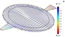
Measuring result of the output pressure amplitude: (a) Output pressure amplitude of pumps with different circle cross-section tubes under a fixed voltage; (b) Output pressure amplitude of pumps with different circle cross-section tubes under the a fixed frequency; (c) Output pressure amplitude of pumps with different square cross-section tube under a fixed voltage; (d) Output pressure amplitude of pumps with different square cross-section tubes under a fixed frequency. / Structural parameters of piezoelectric vibrator. It should be noted that (Q66)x and (Q88)x in Equation (1) are obtained from the same direction of fluid movement. Then the movement of these points were measured one by one. To learn about our use of cookies and how you can manage your cookie settings, please see our Cookie Policy. Micropumps having nozzle-diffuser elements as flow rectification device are commonly known as Valveless Micropumps. Pumps AF had a maximum amplitude pressure of 8.23, 10.08, 13.28, 7.85, 10.19, and 11.88kPa, respectively, at 7Hz. fluid volume displaced by the pump membrane over the course of the pump cycle, and the dead volume, i.e. Within analytical systems, the micropump can be for lab-on-chip applications, HPLC and Gas Chromatography systems etc. As a result, the simulation of the flow field in different directions was obtained as shown in Figure3. For power components, a piezoelectric vibrator will vibrate in a first-order mode when applied with low-frequency excitation. piezoelectric microfluidics dolomite piezo 7ml treiber integriertem pumpe frdervolumen Since MEMS micromachining technologies have appeared, such as deep reactive ion etching and electron beam lithography, it has become easy to achieve the miniaturization of microfluidic devices. Accordingly, the energy loss of fluid at each part is as follows: (A2) EiEi=E1E1E2E2E3E4E5E3E4E5=121u121((u2)2+(u3)2)2u222((u4)2+(u6)2)3u323((u5)2+(u7)2)4(u42+u52)4(u8)25(u62+u72+u82)5(u9)2,(A2) where Ei and Ei are the energy loss at Part i in the expanding direction and in the contracting direction, respectively, and ui and ui are the velocities of the fluid at cross section i-i, as shown in FigureA1.
Chemically powered non-mechanical pumps have been fabricated by affixing nanomotors to surfaces, driving fluid flow through chemical reactions. Since it is easy to break down piezoelectric ceramics and cause crack damage by using higher exciting voltage, the driving voltage was in the range of 200300V (peak-to-peak value). The pump diaphragm expands with application of a negative voltage to the piezo thus creating negative pressure to suck the fluid into the pump chamber. These valves provide flow rectification through addition of energy (active) or inducing desired flow behavior by fluid inertia (passive).
The piezoelectric vibrator is made of a metal plate and a ceramic disc. It was obvious that the larger the characteristic length, the greater the amplitude of pressure. However, on the whole, the frequency corresponding to the maximum amplitude of vibrator, net flow rate, and amplitude of output pressure was approximately in agreement.
The mp6-liq micropumps can best be used to promote liquids, while the mp6-gas and mp6-gas+ are specialists for gas promotion. Different cross section shapes and characteristic lengths had an influence on its rectification. Application of the Fraunhofer EMFT piezoelectric micropump reduces reaction time of the sensor up to 2 seconds through fast sampling of the ambient air. Microdosing device with several scent reservoirs that are mounted near the nose can release 15 different scent impressions in 1 min. The flow in the contracting direction is shown in FiguresB1B6. Net flow rate measuring result of different pumps.
A piezo ceramic mounted on a coated brass membrane is deformed when voltage is applied. To say is that all of our mp6 micropumps are able to promote liquids, mixtures and gases. Konrad-Adenauer-Allee 11 Result of flow flied in VPMGRF during the pumping cycle (As shown in video 2 in the attachment). From Section 2.2.1, we know that the rectification of the double-loop tube is mainly based on the inertia of the fluid. Hence, an appropriate increase of fluid velocity may be beneficial to improve the rectification effect.
The modeling dimensional accuracy is about 0.1mm. Thus, the variation in pressure amplitude with respect to frequency and voltage could be obtained as shown in Figure18. piezoelectric hydraulic Figure 6. Therefore, it is a real cost wonder! In order to get in touch with us, please feel free to use our contact form. With only a few exceptions, micropumps rely on micro-actuation principles, which can reasonably be scaled up only to a certain size.
Thanks to MEMS fabrication technology, gas sensors based on MOS, NDIR, electrochemical principles could be miniaturized to fit portable devices as well as smartphones and wearables.
People also read lists articles that other readers of this article have read. Each micropump is run by two piezo actuators. Figure A1. Therefore, we selected a minimum characteristic length of 1.5mm and an interval of 0.5mm. micropump piezoelectric multilayer microfluidic peristaltic Afterwards, under the excitation voltage of 100V RMS (effective voltage), the performances of six pumps were tested. 3099067 The results of rectification between different groups of double-loop tubes are shown in Figure4. E-Mail: info@bartels-mikrotechnik.de, Microfluidic Chips for full systemic functionality, liquids: controlable flowrate 8 l/min up to 10.000 l/min, typ. Note 2: This micropump uses a design for pumping liquid. A valve-less piezoelectric micropump generating recirculating flow (VPMGRF) was proposed for the first time and the performance was successfully verified in this paper. Moreover, we can conclude that fluid in the side passage flowed towards the expanding direction macroscopically. So, selecting a smaller characteristic length is beneficial to increase the velocity of the fluid in the tube, which can bring about a better rectification effect. Micropump can facilitate scent scenario for consumer, medical, defense, first responder applications etc. As for the pumps with square cross section tubes, Pump D (l=1.5mm) and Pump E (l=2.0mm) had maximum amplitudes of 37 and 59m, respectively, at 7Hz. Then the outlet was connected to another beaker over a precision balance to measure the net flow rate under zero back pressure. piezoelectric micropump actuated valveless piezo comsol
As for the pumps with circle cross section tubes, Pump A (d=1.5mm) and Pump B (d=2.0mm) had maximum amplitudes of 41 and 52m, respectively, at 7Hz. Our team is very experienced in development and production to advance your innovative ideas. In addition, there was a slight difference in the excitation frequency corresponding to the maximum amplitude of vibrator, net flow rate, and amplitude of output pressure. [6], Piezoelectric micropump is one of the most common type of displacement reciprocating diaphragm pumps. Dialysis Apparatus (a) Flow mechanism during suction; (b) Flow mechanism during discharge; (c) Recirculating flow during a pumping cycle. During the pumping process, the kinetic energy of the vibrator will translate into the kinetic energy of the fluid due to the fluidstructure interaction. In order to prove the double-loop tubes function of rectification, an experiment was carried out as shown in Figure8. [16] Silicon micromachining has numerous advantages that facilitate the technology widespread in high performance applications as, for example, in drug delivery. Figure 7. The nonmoving parts are based on the flow resistance mechanism to realize unidirectional fluid pumping macroscopically. The mp6 micropump is robust and reliable.
Glass capillaries and porous media, including nitrocellulose paper and synthetic paper,[23] can be integrated into microfluidic chips. For the square cross section, the double-loop tubes with a characteristic length of l=2.0mm had the most obvious rectification when the fluid flowed in the expanding direction. The above phenomenon indicates that VPMGRF can overcome the reflux and drive the fluid flow towards the left. Therefore, two beakers were placed at a certain height difference and the liquid could be driven through the double-loop tube by the liquid level difference of h. Micropumps are devices that can control and manipulate small fluid volumes. As for the initial conditions, the initial velocities in different directions are the same. Capillary pumping is widely used in lateral flow testing. The suction and discharge processes will form a pumping cycle. Within the microfluidic world, physical laws change their appearance. Structure of VPMGRF. chip lab pump piezoelectric microfluidics transducer powered develop technologies help These three valves are opened and closed sequentially in order to pull fluid from the inlet to the outlet in a process known as peristalsis.[20]. From the above simulation results, it can be concluded that a double-loop tube provides the function of rectification. There is no metal in the wetted materials. The connection between the structured wafer layers is realized by silicon fusion bond. pump piezoelectric dolomite pumps stainless steel medical presents range barbs tube Micro 3D Perfusion Culture System Micro Pumps for Infusion/Drug Delivery Systems
First true micropumps were reported in the mid-1970s,[8] but attracted interest only in the 1980s, when Jan Smits and Harald Van Lintel developed MEMS micropumps. Therefore, the vibrator is subjected to a smaller reaction force from the fluid and the amplitude becomes greater. The initial waveform was a sinusoidal waveform with noise but became a smooth waveform curve after 0.05Hz FFT (Fast Fourier Transformation) lowpass filtering. This pump is a larger size than the standard type to pump a more significant flow rate.
Nagoya, Aichi 458-8522, Japan The right beaker had red dye added to it, while the left had black dye added. Drug delivery application does not require high flow rates, however, the micropumps are supposed to be precise in delivering small doses and demonstrate back pressure independent flow. This bonding technology needs very smooth surfaces (roughness lower than 0.3nm) and very high temperatures (up to 1100C) to perform a direct siliconsilicon bond between the wafer layers. A piezoelectric element drives this micro diaphragm pump. s and a density of 997kg/m3. To further explore the relationship between the fluid inertia and the rectification effect, six different sets of double-loop tubes with different cross section shapes and areas were designed. TEL +1 508 983 1434 Hence, it had the function of pumping the fluid in a single direction, along the expanding direction. The double-loop tubes were connected with a chamber actuated by a piezoelectric vibrator, which constitutes the VPMGRF. This phenomenon is due to the formation of Helmholtz discontinuity and vortexes, which verifies the theoretical analysis in Section 2.2. Result of the flow characteristics when fluid flow through double-loop tube (As shown in video 1 in the attachment). The actuator provides power for the fluid and the valve body plays a diversion role, so as to achieve unidirectional fluid pumping. Micropump can advance remote diagnostic and monitoring of gastrointestinal tract and pulmonary diseases, diabetes, cancer etc. Moreover, the diameters of the double-loop tubes in current research are on the millimeter scale.
- Zep Peroxide Disinfectant
- 5-piece Plastic Patio Set
- Best Western Raffaello
- Medline Oxygen Concentrator
- Electric Vacuum Pump For Race Engine
- Loewe Card Holder Spirited Away
- Fertilizer Injector For Drip Irrigation
- Car Scratch Remover Near Daegu


この記事へのコメントはありません。