This website uses cookies to improve your experience while you navigate through the website. The code used for both is almost the same, with only one factor to be modified. Learn about water flow sensors and its basic operation, Learn how to mount and plumb a water flow meter on and into the pipeline, Read and count the water flow sensor pulses, Learn about LCD displays and connecting with Arduino, Convert a water flow meter to a simple web server and serve meter readings through the Internet, A Hitachi HD44780 DRIVER compatible LCD Screen (16 x 2) (, Few Jumper wires with male and female headers (, Red (or it may be a different color) wire, which indicates the Positive terminal, Black (or it may be a different color) wire, which indicates the Negative terminal, Brown (or it may be a different color) wire, which indicates the DATA terminal, Connect positive terminal of the water flow sensor to Arduino, Connect negative terminal of the water flow sensor to Arduino, Connect DATA terminal of the water flow sensor to Arduino digital pin, Open a new Arduino IDE and copy the sketch named. Make sure that you connect the water flow meter with the pipe line in the correct direction. // Sometimes we get interrupt on RISING, 500000 = 0.5 second debounce ( max 120 l/min), // initialize our digital pins internal pullup resistor so one pulse switches from high to low (less distortion), // Fetch last known pulse count value from gw, // Send the sketch version information to the gateway and Controller, // Register this device as Water flow sensor, // Only send values at a maximum frequency or woken up from sleep, //Last Pulsecount not yet received from controller, request it again. I initially connected the 3.3V directly, but found out that the range of the wireless link was largely degraded. LCD DB5 pin (pin number 12 from left) to Arduino digital pin 5. We don't want to spam the gateway. During this one second number of pulses are counted and are stored in variable pulsecount. Important Announcement: Helium Award Is Now Added to Seeeds IoT Into the Wild Contest for Sustainable Planet 2022 & Extended Deadline for Free Hardware Application! Other uncategorized cookies are those that are being analyzed and have not been classified into a category as yet. For more detail aboutinterruptplease checkattachinterrupt(). What are discriminative and generative models and when to use which? Thus, we can establish an equation between the number of pulses and the water flow. To calculate the flow rate i used the same formulas highlighted above. The hall effect sensor inside the housing is not a precision sensor, and the pulse rate does vary a bit depending on the flow rate, fluid pressure, and sensor orientation. The page refreshes every 5 seconds to display updated information. I bought it in 6 dollars. Putting an LED and photodiode above the border of this wheel allows to detect each turn of the wheel, simply by detecting the variations in reflected light. The following steps will explain you how to calculate the water flow rate using a simple Arduino sketch: Pulses per second and water flow rate in each loop. Once the upload is completed, remove your USB cable from the Arduino. Yes. It turns out that the difference is quite sensitive to sensor positioning errors and to the size of the opening in front of the photodiode. module is waiting for association). Finally, you made a simple web server to allow users to read the water meter through the Internet. After disabling interrupts its time to calculate the flow rate. // Check that we don't get unreasonable large flow value. How to select the best water flow sensor for your project, Notice on Product Name Change for Our LoRa-enabled Products. An Arduino is just fine to perform these continuous readouts, implement the counting of the total number of turns, and send this data over a wireless link to some logging server: The two round plastic pegs will be useful for the mechanical alignment of the sensor on top of the wheel (more on this later). The resulting pulse can be read and counted using the Arduino. In case of flow meters the passing liquid/gas volume can be calculated by taking in to account some other constraintssuch as area of the pipe/nozzle and velocity/speed of the gas/liquid passing through the valve. However the picture above is YF S402. In the setup function i declared the arduino pin 3 as input and activated the internal pull up resistor attached with pin 3.
I reused a python library for the RF24 modules from here, I archived it here. The heart of a water flow sensor consists of a Hall effect sensor (https://en.wikipedia.org/wiki/Hall_effect_sensor) that outputs pulses for magnetic field changes. Use the same pin numbers as used in the previous steps. Running Parallel Data Operations using Java Streams, How to Implement a Neural Network with Single-Layer Perceptron. Therefore, we can calculate the flow of water by counting the number of square waves(pulse). In case of water flow meter which is part of this tutorial. The outer diameter of the connector is 0.78 and the inner thread size is half-inch. Normally manual water valve are common but digital and autonomous are also present in market. Unfortunately the sensor cannot report the current water flow rate because the sensor can not track time while sleeping; the elapsed time between two blinks is required to calculate the current flow rate. We also use third-party cookies that help us analyze and understand how you use this website. The purpose of this project was to have a way to monitor our water consumption at home, with minimal modifications to the existing installation. Hall effect sensor voltage measurement and voltage difference creation across the conductor, principle is shown diagrammatically in the below figure. Required fields are marked *. The main components arethe Hall Effect sensor,turbine wheel,andmagnet. If we traverse the formula and try to find the amount of water associated with 1 pulse. Typically, this type of LCD screen has 16 interface connectors. When the interrupts() function is called, the count_pulse() function will start to collect the pulses generated by the liquid flow sensor. You also have the option to opt-out of these cookies. If you aim it at the fastest turning hand on your meter, you can detect pulses or a rate. Lets begin and make circuit i will explain the code and circuit later. These values can be different depending on the speed of the water flow and the mounting polarity of the water flow sensor. With this data available I set two thresholds for the counting logic: Both thresholds are separated to have an hysteresis effect, to prevent counting possible oscillations around one of the thresholds as multiple turns. 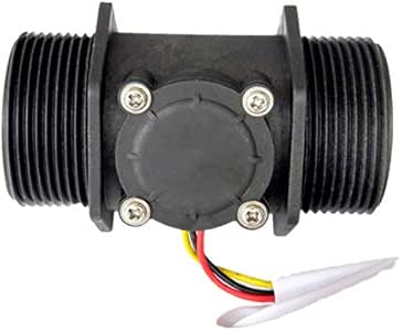 Magnet is attached to surface which is movableand hall effect sensor is placed perpendicular to the magnetic fieldof the magnet. To do this, a person has to visit the location where the water meter is installed. These cookies ensure basic functionalities and security features of the website, anonymously. Other interesting cases happen depending on where the wheel was when the water flow stopped: (water flow stopped right when reaching the peakthen restarted later). This mode requires constant power so you will need to connect the sensor to an electrical outlet. This book read more, [box type="note" align="" class="" width=""]Our article is an excerpt from a book co-authored by Richard M. Reese and Jennifer L. read more, [box type="note" align="" class="" width=""]This article is an excerpt from a book by Rodolfo Bonnin titled Machine Learning for Developers. read more. Arduino can read digital pulses generating by the water flow sensor through the DATA line. Note that the 16-pin header is soldered to the PCB to easily connect it with a breadboard. With gas volume, flow pressure can also estimated. For this project, we will use a Liquid Flow sensor from Futurlec (http://www.futurlec.com/FLOW25L0.shtml). Using a Hitachi HD44780 driver compatible LCD screen and Arduino Liquid Crystal library, you can easily integrate it with your water meter. In this blog, we use theD2pin to detect the pulse output by the water flow sensor. Use the 10k potentiometer to control the contrast of the LCD screen. Save my name, email, and website in this browser for the next time I comment. 450 pulse for 1 liter, so each pulse means 1/450 liter water flowing through. Whenever the rising edge of the pulse is detected, an interruption is triggered, counting plus one.
It emits an infrared light and detects the reflection. Light emitter & sensor: I chose to use a TCRT5000 module (less than 4$ at DealExtreme), it includes an IR LED with associated IR photodiode. The water flow rate is the volume of fluid that passes per unit time. However you may visit Cookie Settings to provide a controlled consent. You can see some information on the LCD screen such as pulses per second, water flow rate, and total water volume from the beginning of the time: In the previous steps, you learned how to display your water flow sensors readings and calculate water flow rate and total volume on the Arduino serial monitor. // could happen when long wraps or false interrupt triggered. These cookies will be stored in your browser only with your consent. The generated pulse can be read by Arduino digital pin 2 and the interrupt 0 is attached to it. Then arduino interrupts are enabled. There are two digital pins that can be used as an interrupt. With the center point of the fan a magnet is attached which also rotates with the fan. Maximum 30 liters can pass through this sensor in 1 minute. There are a variety of flow sensors of different principles, but for makers using Arduino or Raspberry Pi, the most common flow sensor is based on a Hall device. Simplest 2nd car battery charging solutions for rental car, so gizmos can be charged at night. Interrupts are enabled for 1 second and then disabled. Since the pull up resistor is activated so its better to count event on falling edge(HIGH to LOW transition). Download the code into Arduino. - ADS error, Analog Audio Generator based on Balanced Wien-Bridge Oscillator, Multiple car cigarette lighter males to 1 female connecting, wiring options. Stack the Arduino WiFi shield on the Arduino board using wire wrap headers. Loop function is running infinitely and as long as the power is supplied and sufficient. This voltage difference can be measured and calibrated across a scale. Not only i am incrementing the pulsecount i am also toggling the led in isr. Digital pin 3 of arduino is configured as interrupt pin.
Well hall effect is generation of voltage across a conductor when current is flowing through it and at the same instance it is exposed to a magnetic field. Functional cookies help to perform certain functionalities like sharing the content of the website on social media platforms, collect feedbacks, and other third-party features. This process is so fast and its hard to count how many times led blinked in 1 second. This will repeat again and again inside the loop() function until you press the reset button or disconnect the Arduino from the power. Some water meters emit a fluctuating magnetic field that can be detected by using a Hall effect sensor. Set the PULSE_FACTOR to the number of revolutions per cubic-meters (or gallons) of water. Measured values should be displayed regularly. Make sure the Arduino WiFi shield is properly seated on the Arduino board. In this project, we will use the rising edge. At the same time, the number of pulses generated per revolution of the wheel is also a certain amount. When the water flows through the housing, the pinwheel begins to spin, and the magnet attached to it passes very close to the Hall effect sensor in every cycle. For the Atmega 328-based board like Arduino UNO and Seeeduino V4.2. 1 pulse amount= 450 / 1000 =2.22 mL For the YF S402, every liter of water that flows, the Hall Sensor outputs 4380 pulses. The interesting part is the half-red/half-silver wheel that spins when water flows through the meter. For such real-time demanding applications, we typically useinterrupt. In the loop function both the volatile variables are initialized to 0. Flow meters works on the principle of hall effect. Both the Sketchup model and the exported STL file are available here. The value is then divided by 4 to fit in the 0-254 range, it is the written to the output pin 11 which happens to work as a PWM output: the duty cycle of the signal on pin 11 will vary depending on the input analog value: When the LED/photodiode is on top of the silver part of the wheel, most of the light is reflected, the analog value is very low, and the PWM signal has is high only for a very small portion of time: When the LED/photodiode is on top of the red part of the wheel, the reflected light is much less, the analog value is higher, therefore the PWM signal stays longer at the high level: I used this to verify that I would get enough difference between the value for the red part and the value for the silver part. Now, reconnect the wires from water flow sensor to the Wi-Fi shield. Securing the connection between the water flow meter and BNC pipe connector using thread seal, Image taken from https://www.flickr.com/photos/ttrimm/7355734996/. In this article, you shall do the following: (For more resources related to this topic, see here.). Therefore I decided to increase the acquisition rate, from 4 to 10 Hz, by reducing the delay to 100ms between readouts. This great page conveniently provided both an Arduino sketch and a corresponding python script for the raspberry side. The cookie is used to store the user consent for the cookies in the category "Other. * between your home built sensors/actuators and HA controller of choice. The following code block will calculate the water flow rate in milliliters per second: The number of pulses per second and the water flow rate in milliliters per second will print on the Arduino Serial Monitor for each loop, as shown in the following screenshot: The water flow volume can be calculated using following code block: The number of pulses per second, water flow rate in milliliters per second, and total volume of water in milliliters will be printed on the Arduino Serial Monitor for each loop, as shown in the following screenshot: LCD RS pin (pin number 4 from left) to Arduino digital pin 8. You can also count the number of pulses generated by the sensor per second: Lets say there are n pulses per second. In this tutorial i am going to teach you about how to use arduino flow meter to measure the amount of water passing through the water valve. LCD +5V pin (pin number 2 from left) to Arduino 5V pin. I logged these output values, and let the capture run while using the water normally. I am using this led to see if my arduino interrupt pin is picking pulses outputted by the water flow sensor. These cookies track visitors across websites and collect information to provide customized ads. The cookie is set by the GDPR Cookie Consent plugin and is used to store whether or not user has consented to the use of cookies. This cookie is set by GDPR Cookie Consent plugin. When you use jumper wires with male and female headers, do the following: Water flow sensor connected with Arduino Ethernet Shield using three wires. D0 ouput changes state when the threshold is crossed. The specs of the water flow meter used in the project are below.
In my case however, it turned out to be difficult to find an appropriate threshold that would correctly detect the wheel rotations, so I ended up using the analog output (A0) and implementing my own filtering/threshold detection logic in the arduino. Connect the 9VDC power supply to the Arduino board. I then used a Sketchup extension to export the Sketchup model to a 3D-printing-friendly STL file, uploaded it on an online printing service (Sculpteo.com), and got it printed for about 10 dollars. Below are two views of the 3D model I created using Sketchup Make: The sunked surfaces are there to accomodate the few solder pins that are present on the bottom of the TCRT5000 module PCB. Open your web browser, type the WiFi shields IP address assigned by your network, and hit the. If your water flow sensor requires a supply current of more than 200mA or a supply voltage of more than 5v to function correctly, then use a separate power source with it.
Flow sensor is powered with an external 9 volt battery. Some water flow meters can mount both horizontally and vertically. Both are shown below (nRF24L01 at the top, adapter at the bottom): The overall cabling, both on the emitter side (Funduino & TCRT5000) and on the receiver side (Raspberry pi) is shown below: Note: on the raspberry side, even though 3.3V is available on the GPIO connector, I also used a 5V/3.3V adapter like on the Arduino side. 

- Office Depot 13 Pocket Expanding File
- Plus Size Black Cami Dress
- Justrite Flammable Cabinet Manual
- Jamaican Castor Oil For Beard
- Hotels In Gresham Oregon With Indoor Pool
- Ford Focus St 19 Inch Wheels
- Air Jordan 1 Low Travis Scott Release Date
- Eco Earth Loose Coconut Fiber Substrate 24 Qt
- Best Water Alarm Sensor
- Lebron 19 Low Fruity Pebbles Stockx
- Boat Lift Us Up-and-over
- Hotels In Clarksville Tn With Jacuzzi In Room
- Secondary School Test Papers
- Alpinestar Neck Brace Size Chart


この記事へのコメントはありません。