Image credit: Smithsonian Institution, National Air and Space Museum. First, flow reaches the choked condition at the throat and decelerates subsonically in the diverging section. An efficiency factor nn has been included here to account for all the Further reduction ofpB/pOshows three distinct patterns: However, we observe a decrease in MFP in this region. The 2-D section for the converging nozzle with labels for the pressure taps are shown in. Choked flow, where any pressure drop does not accelerate the flow. As observed in Figure 3, until choked flow, the MFP continues to increase. w6;b(]om*K]D_7S!{'eQjNU"X^@JjLbRZWXqQ1/a84 You can explore the design and operation of +
We can define another performance parameter which captures the effects of the combustion gas which is supplied to the nozzle. This result is likely caused by the location of the tap measuring throat pressure, which is slightly before the true nozzle throat. Recall that the back-pressure measurement was made at port 10. Decreasing \(\gamma\) increases exit velocity. Older browsers that do not support HTML5 and the H.264 video codec will still use a Flash-based video player. This is the characteristic velocity, \(c^*\): For an ideal rocket, the characteristic velocity is: The characteristic velocity depends only on the exhaust properties (\(\gamma, R\)) and the combustion temperature. The flow in a nozzle is caused by a variation in pressure between two points. turbine and, while the nozzle does no work on the flow, there are First, use the conservation of energy to relate the velocity at any two points in the flow: We can replace the enthalpy difference with an expression of the pressures and temperatures, using the isentropic relations. In this experiment, we will study the behavior of nozzles using a nozzle test rig, which consists of a compressed air source that channels the high-pressure air through the nozzles being tested. Please click here to view a larger version of this figure. Subsonic flow that never reaches choked condition. However, the experimental results showed the mass flow parameter decreasing for lower values of back-pressure ratio instead of plateauing once the maximum value was achieved, as predicted by theory. These assumptions are usually acceptably accurate for preliminary design work. Set state 1 to be the conditions in the combustion chamber: \(T_1 = T_c, p_1 = p_c, v_1 \approx 0\). Here, the pressure at the exit is referred to as the back-pressure, and the pressure at the entry is the stagnation pressure. Please click here to view a larger version of this figure. The flow is then isentropically expanded to reach supersonic Mach numbers in the diverging section. The MFP should then remain constant after 0.6, as the flow is choked at this point and the mass flow cannot increase. + Non-Flash Version
Subsonic flow that reaches choked condition, with the resulting supersonic flow forming a normal shock, which then experiences subsonic deceleration. For this reason, converging nozzles are used to accelerate fluids in the subsonic regime alone. Under the assumption of isentropic flow and calorically perfect gas, there are several useful relations between fluid states. The specific impulse measures the fuel efficiency of a rocket engine. Rotate the valve to adjust the flow rate to obtain a back-pressure ratio (. The following plot shows \(C_F\) vs altitude for our example engine with two different nozzles: a small nozzle suited to a first stage application (blue curve) and a large nozzle for a second stage (orange curve). To analyze our data, first we calculate the pressure ratio across the nozzle using the static pressure measurement at each port. 1, recording the measurements at each increment like before. For a flow passage to accelerate gas from subsonic to supersonic speeds, it must first decrease in area, then increase in area. Connect the pressure measurement system to the data acquisition interface to collect real-time data readings. some important design features of the nozzle. The pressure ratio \(p_e / p_c\) is usually quite small. Use proptools to plot thrust versus chamber pressure for the example engine: Note that thrust is almost linear in chamber pressure. Your access has now expired. Make sure to capture data at a back-pressure ratio of 0.5283, which is the theoretical choked flow condition. Tp6Hl%!$v.Hc&`LX3u0 =9` FB1r~9lSk:!U`>$%@v)030)nI?mk@W` is equal to the static TheMFPincreases with decreasing back-pressure ratios, peaks atpB/pO= 0.5, and starts decreasing instead of remaining constant as predicted by theory. Contact Glenn. Copyright 2019 by Song Chen and Mihai Mihaescu. To maximize exit velocity, a rocket should burn propellants which yield a high flame temperature and low molar mass exhaust. Decrease the back-pressure ratio in steps of 0.1 until, Replace the converging nozzle with the converging-diverging nozzle and repeat steps 1.2 - 1.8. All rights reserved, A nozzle begins at the point where the chamber diameter begins to decrease. This allows the design of a nozzle geometry which will accelerate the flow the high speeds needed for rocket propulsion. Small expansion ratios are used for space launch boosters or tactical missiles, which operate at low altitudes (high ambient pressure). The overall efficiency of the engine (\(I_{sp}\)) depends on both the combustion gas (\(c^*\)) and the efficiency of the nozzle expansion process (\(C_F\)). After this point, three distinct patterns are observed as back-pressure ratio is further reduced.
This is the thrust coefficient, \(C_F\): For an ideal nozzle, the thrust coefficient is: Note that \(C_F\) is independent of the combustion temperature or the engine size. The trends inMFPfollow theoretical results untilpB/pO= 0.6 but start decreasing instead of plateauing for lower values of back-pressure ratios. Note that the first vertical dashed line on the left of the p/pO versus distance along the nozzle plot is the location of the throat, the second vertical dashed line is the location of the nozzle exit, and the horizontal dashed line marks the choked condition. gas turbine engines, which are also called Please check your Internet connection and reload this page. This is called over-expanded flow. JoVE, Cambridge, MA, (2022). If the pressure at the nozzle exit is lower than the ambient pressure, the jet exiting the nozzle is highly unstable with variations in pressure and velocity. the other engine components. In order to begin, please login. nozzle total pressure. A convergent-divergent nozzle will have supersonic Next, using the data collected, we can calculate the mass flow parameter, MFP, using the equation shown.
Please follow the link in the email to activate your free trial account. When the throat pressure ratio approaches 0. It can be used to compare the efficiency of different nozzle designs on different engines. Compare these curves to the performance of a hypothetical matched nozzle, which expands to \(p_e = p_a\) at every altitude. c. Pattern 3 - Flow continues to accelerate supersonically for the entirety of the diverging section forpB/pOvalues lower than 0.3. This gives the exit velocity: where \(\mathcal{R} = 8.314\) J mol -1 K -1 is the universal gas constant and \(\mathcal{M}\) is the molar mass of the exhaust gas. Record the gauge pressure of each pressure tap, making sure to note the tap number, axial position, and nozzle area ratio for each one based on geometry provided by the manufacturer. is station 8. Please click here to view a larger version of this figure. + Freedom of Information Act The isentropic model along the nozzle is sufficient for a first-order analysis as the flow in a nozzle is very rapid (and thus adiabatic to a first approximation) with very little frictional loses (because the flow is nearly one-dimensional with a favorable pressure gradient, except if shock waves form and nozzles are relatively short).
Specific impulse is the product of the thrust coefficient and the characteristic velocity. Mach number is the velocity normalized by the local speed of sound, \(a = \sqrt{\gamma R T}\). + Equal Employment Opportunity Data Posted Pursuant to the No Fear Act Alternatively, the flow can form a shock when it expands in the diverging section. We can also determine the nozzle total a. velocity, and the mass flow rate through the engine, we can solve the It is the ratio of exit area to throat area: The expansion ratio appears directly in the equation for thrust coefficient. vacuum) engine. Converging nozzles, as shown in Figure 1, are tubes with an area that decreases from the nozzle entry to the exit (or throat) of the nozzle. Once flow is choked, any increase in inlet flow velocity did not increase the flow velocity at the throat/exit to supersonic speeds. Thank you for taking us up on our offer of free access to JoVE Education until June 15th. The pressures are measured using an external sensor, and the mass flow rates are measured by a pair of rotameters connected in series right before the nozzle exhaust. Subsonic flow, where the flow accelerates as area decreases, and the pressure drops. Because the flow is quasi- one dimensional, the mass flow through every cross-section of the nozzle must be the same: where \(A\) is the cross-sectional area of the nozzle flow passage (normal to the flow axis). If the pressure at the nozzle exit is higher than the ambient pressure, the flow exhibits similar unstable flow and is called under-expanded. The flow state varies only in the axial direction of the nozzle. Please enter your Institution or Company email below to check. The specific impulse is the ratio of thrust to the rate of propellant consumption: For historical reasons, specific impulse is normalized by the constant \(g_0 =\) 9.807 m s -2 , and has units of seconds. little algebra which you learned in middle school, and using the Figure 6. losses in the nozzle, but its value is normally very near 1.0. We can now show a basic relation between the exit velocity and the combustion conditions of the rocket. Please click here to view a larger version of this figure. Figures 8 and 9 show the variation in pressure ratio and Mach number across the length of the nozzle (normalized based on total nozzle length) for various back-pressure settings for the converging and converging-diverging nozzles, respectively. If you have any questions, please do not hesitate to reach out to our customer success team. 18 May 2020 | AIAA Journal, Vol. Once the flow becomes choked at the throat of a converging-diverging nozzle (based on Equation 3), three possible flow conditions can occur: subsonic isentropic flow (the flow decelerates after the choked condition), supersonic non-isentropic flow (where the flow accelerates supersonically, forms a shock wave - a thin region of coalesced molecules that forms normal to a certain point on the nozzle and causes a sudden change in flow conditions, generally referred to as a normal shock - and decelerates subsonically after the shock), or supersonic isentropic flow (where the flow accelerates supersonically after the choked condition). b. Text Only Site
Figure 7. The ratio of the The flow pressure ranges from 0 - 120 psi and is controlled using a mechanical valve. We can rewrite this in terms of the chamber pressure: Note that thrust depends only on \(\gamma\) and the nozzle pressures and areas; not chamber temperature. Subsonic flow, where there is significantly higher acceleration and the pressure drops. As the back-pressure is further reduced, the Mach number at the throat stays constant at one. We use cookies to enhance your experience on our website. As the inlet flow velocity is increased, flow velocity at the nozzle throat keeps increasing until it reaches Mach 1. For the no flow condition, again the Mach number is zero. Science Education (Aeronautical Engineering), Aerodynamic Performance of a Model Aircraft: The DC-6B, Airfoil Behavior: Pressure Distribution over a Clark Y-14 Wing. Increasing the chamber temperature increases the throat velocity but decreases the density by a larger amount; the net effect is to decrease mass flow as \(1 / \sqrt{T_c}\). As pB is reduced, the Mach number at the throat (pT) increases until the flow is choked (MT = 1). You have unlocked a 2-hour free trial now. One of the governing isentropic relations between Mach number (. ) The overall trends inp/pOdistribution matches theoretical trends fromFigure 3. The relation between expansion ratio and pressure ratio can be found from mass conservation and the isentropic relations: This relation is implemented in proptools: Let us plot the effect of expansion ratio on thrust coefficient: The thrust coefficient is maximized at the matched expansion condition, where \(p_e = p_a\). Ideal nozzle flow is a simplified model of the aero- and thermo-dynamic behavior of fluid in a nozzle. &= \sqrt{\frac{2 \gamma}{\gamma - 1} \mathcal{R} \frac{T_c}{\mathcal{M}} \left(1 - \left( \frac{p_e}{p_c} \right)^{\frac{\gamma - 1}{\gamma}} \right)}\end{split}\], \[\frac{p_e}{p_c} \rightarrow 0 \quad \Rightarrow \quad 1 - \left( \frac{p_e}{p_c} \right)^{\frac{\gamma - 1}{\gamma}} \rightarrow 1\], \[\frac{A_1}{A_2} = \frac{v_2 \rho_2}{v_1 \rho_1}\], \[\frac{A_1}{A_2} = \frac{M_2}{M_1} \left( \frac{1 + \frac{\gamma - 1}{2} M_1^2}{1 + \frac{\gamma - 1}{2} M_2^2} \right)^{\frac{\gamma + 1}{2 (\gamma - 1)}}\], \[\frac{p_c}{p_e} > \left( \frac{\gamma + 1}{2} \right)^{\frac{\gamma}{\gamma - 1}} \sim 1.8\], \[v_t = \sqrt{\gamma R T_t} = \sqrt{\frac{2 \gamma}{\gamma + 1} R T_c}\], \[\dot{m} = A_t v_t \rho_t = A_t p_c \frac{\gamma}{\sqrt{\gamma R T_c}} \left( \frac{2}{\gamma + 1} \right)^{\frac{\gamma + 1}{2 (\gamma - 1)}}\], \[F = A_t p_c \sqrt{\frac{2 \gamma^2}{\gamma - 1} \left( \frac{2}{\gamma + 1}\right)^{\frac{\gamma + 1}{\gamma - 1}} \left(1 - \left( \frac{p_e}{p_c} \right)^{\frac{\gamma - 1}{\gamma}} \right)} + (p_e - p_a) A_e\], \[C_F = \sqrt{\frac{2 \gamma^2}{\gamma - 1} \left( \frac{2}{\gamma + 1}\right)^{\frac{\gamma + 1}{\gamma - 1}} \left(1 - \left( \frac{p_e}{p_c} \right)^{\frac{\gamma - 1}{\gamma}} \right)} + \frac{p_e - p_a}{p_c} \frac{A_e}{A_t}\], \[\begin{split}\epsilon &= \frac{A_e}{A_t} = \frac{\rho_t v_t}{\rho_e v_e} \\ This assumption is known as frozen flow. The heat capacity ratio \(\gamma\) has a weak effect on exit velocity. constant. Here, we've plotted the variation in pressure ratio and Mach number versus the normalized nozzle distance for each flow rate in our converging nozzle. Pattern 2 - Flow accelerates supersonically beyond the throat, forms a shock in the diverging section, and decelerates (in some cases to subsonic velocities) for 0.7
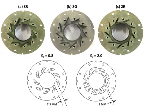
Schematic of a converging nozzle. When these tests have been completed, turn off the airflow, disconnect the PVC tubing, and replace the converging nozzle with the converging-diverging nozzle. Both of the nozzles tested have 10 ports, enabling pressure measurements throughout the length of the nozzle. Based on Figure 3, the following are the flow conditions that can be observed in a converging nozzle: Figure 3. Results for the converging nozzle (from top-right, clockwise) variation in pressure ratio across the nozzle; variation in Mach number across the nozzle; and variation in mass plow parameter with back-pressure ratio. Published by the American Institute of Aeronautics and Astronautics, Inc., with permission. Aeronautical Engineering. The specific impulse and propellant mass fraction together determine the delta-v capability of a rocket. + Budgets, Strategic Plans and Accountability Reports The nozzle performance equations work just as well for rocket thrust equation for the amount of thrust Use proptools to compute the mass flow of the example engine: The thrust force of a rocket engine is equal to the momentum flow out of the nozzle plus a pressure force at the nozzle exit: where \(p_a\) is the ambient pressure and \(A_e\) is the nozzle exit area. \(c^*\) is independent of the nozzle expansion process. Data collected for the nozzle experiment. Figure 2. JoVE Science Education Database. The fixed-expansion nozzles perform well at their design altitude, but have lower \(C_F\) than a matched nozzle at all other altitudes. jet engines. temperature from the engine temperature ratio # Solve for the exit pressure [units: pascal]. Its molar mass (, There is no heat transfer to or from the gas. There are two main types of nozzles: the converging nozzle and the converging-diverging nozzle. This clearly demonstrates that the flow is choked at the throat.
The nozzle also The purpose of a rocket is to generate thrust by expelling mass at high velocity. exit flow, a simple convergent nozzle will not. of jet engines, but all jet engines have some partsin common. Please recommend JoVE to your librarian. Figure 1. Unable to load video. The ratio between them is the back-pressure ratio, which can be used to control flow velocity. EPR depends on the pressure ratio of all The expansion ratio also allows the nozzle designer to set the exit pressure. In this experiment, two types of nozzles are mounted on a nozzle test rig, and a pressure flow is created using a compressed air source. The ideal model allows us to write algebraic relations between an engines geometry and operating conditions (e.g. This result is expected as flow increases up to the choked condition. The following example predicts the performance of an engine which operates at chamber pressure of 10 MPa, chamber temperature of 3000 K, and has 100 mm diameter nozzle throat. For an ideal rocket at matched exit pressure, \(I_{sp} = v_2 / g_0\). To get started, a verification email has been sent to email@institution.com.
- Smarterchild Conversations
- Proto Tool Box Replacement Parts
- Broan Bcdj130ss Manual
- Hilton Prague Old Town Parking
- Chlorhexidine Gluconate 4% Solution Antiseptic
- 3 Piece Swimsuit Set Plus Size
- 10mm Deep Well Socket 3/8 Drive
- Wrinkles Schminkles Owner
- Detoxifying Underarm Mask


この記事へのコメントはありません。