font-size: 10pt;
So, I didn't get the chance to control it via PID. #include 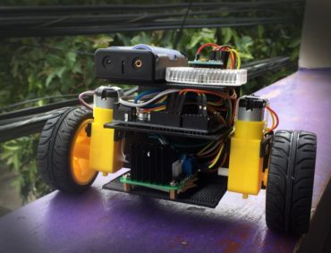 The dimensions of the hole must be equal to that of the wings. align-items: center;
The self-balancing robot building is today an activity that every robot builder can perform with Arduino.
The dimensions of the hole must be equal to that of the wings. align-items: center;
The self-balancing robot building is today an activity that every robot builder can perform with Arduino. 
 Servo m;
I am making the same project. By clicking Accept all cookies, you agree Stack Exchange can store cookies on your device and disclose information in accordance with our Cookie Policy.
Servo m;
I am making the same project. By clicking Accept all cookies, you agree Stack Exchange can store cookies on your device and disclose information in accordance with our Cookie Policy.
It oscillates back and forth, and these oscillations need to be damped. may i know ur servo motor rpm..?????????? You need gyroscope or anything similliar, i believe yes, even interrupt based program (with sensors 2cm above ground) will read 14 "1.36cm" steps (20 / 1.36) each taking 4ms, the loop time is (you are right 60ms), just re edit you answer, and as an evidence a quadcopter loop time is 4ms and i hardly balance (at least DIYs) so expect what a 60ms might do. justify-content: center;
The best answers are voted up and rise to the top, Start here for a quick overview of the site, Detailed answers to any questions you might have, Discuss the workings and policies of this site, Learn more about Stack Overflow the company. endstream Connect the inA, inB, inC, and inD of the motor driver to Arduino Uno.
A fainating discussin iss worth comment. It is also designed in hostile shapes which qualify it to fight. Is Ultrasonic Self Balancing Robot Possible? h{G/5i4PbiEuzpHvus
To power up the motor driver, we will get if from the 5V pin and GND of the Arduino Uno. An ultrasonic sensor is attached to the pipe. text-align: center;
The robot will only use a MPU6050 sensor for evaluating and navigating the terrain, a triple axis accelerometer and gyro for calculating angular velocities and accelerations, and Arduino. delay(25);
Searching in Google for self-balancing robot you can find tons of realizations, with tons of different sensors and control systems.
Here is the Circuit Schematic. We have an ultrasonic sensor, which can measure the distance between the robot and the obstacles in front. Stick it with tape. It only takes a minute to sign up. so the triangle tips over. Make sure to follow the correct polarity. Trying to be at least original, I though to build a self balancing robot with these goals: So I tried to build a self-balancing robot using only one sensor: a Sharp IR distance sensor e nothing else. Travel trading to cover cost and exploring the world. ]~=y1O?0;g?ZOP/>?Z/^YO/_|'7[>@2~y{d
7WW)?\z?sf]|O^xysVRoi_wVk_8}{7o/. By clicking Post Your Answer, you agree to our terms of service, privacy policy and cookie policy. Control toys like a superhero. Thanks for contributing an answer to Robotics Stack Exchange! margin: 0;
%%EOF
We will use this for the input power of our self balancing robot. So finding the right parameters is a patience work. Notice that we used two set of wires.
Self-balancing robot with two ultrasonic proximity sensors and nRF24 communication + remote. Now we have fixed the motor in the T-joint. The same goes for the right side. We will mount a Servo motor on top of it. The robot is now placed vertically on the ground. ScienceDirect is a registered trademark of Elsevier B.V. ScienceDirect is a registered trademark of Elsevier B.V. Navigation of Self-Balancing Mobile Robot through Sensors. Connect with your peers and get expert answers to your questions. To subscribe to this RSS feed, copy and paste this URL into your RSS reader. endobj Four wires are connected from the pins to the microcontroller. And whenever the triangle falls towards the right, the link should be moved left. But, the other sensor is just for equal dead weight, it is not connected. But, somehow we managed to make it balanced a little bit. You can follow any responses to this entry through RSS 2.0. can u send me the modified code using dc motors and ultrasonic sensors, sorry too much time to do this. See this schematic Diagram to double check your wirings. Now we have fixed the motor in the T-joint. We will modify it further. #m__dvc_e5dea2ff39954b968b535e87d5a8617d.document-viewer-message {
When the triangle is upright, its center of gravity remains right above its base. There are two sensors. long duration, cm;
When do we say "my mom made me do chores" and "my mom got me to do chores"? so the triangle tips over. I think that using only one sensor is a limit situation in order to get the balance.
Robotics Stack Exchange is a question and answer site for professional robotic engineers, hobbyists, researchers and students. Probably not - it can take about 60ms to get a reading from those sensors, which is quite slow for the loop updating a balancing robot. Now if the triangle falls on one side, The servo motor will move the weight to the opposite side. Connect SDA and SCL of MPU6050 Accelerometer to i2c pin (A4, A5) of the Arduino Uno. Connect the DC jack adapter to the VIN and GND of Arduino Uno and also connect it to VCC and GND of the motor driver. If a species keeps growing throughout their 200-300 year life, what "growth curve" would be most reasonable/realistic? delayMicroseconds(2);
No gyro, no accelerometer, no other sensors. This is a wheeled self balancing robot. Approach for covering entire floor plan using Arduino-UNO and HC-SR04. background-color: #EEE;
To counterbalance. #1 by Annie Supple on 19 June 2017 - 03:15. The sensor have a 10-80 cm range and it has a trasfer function voltage-distance similar to an hyperbole in the working range, so I tried to put it in the point of maximum sensibility, in order to obtain the maximum voltage variation compared with the distance. endobj This is what it looks like after inserting sensors on both of its wings. hbbd``b`$CC`V@He`Mg|
endstream
endobj
startxref
0
%%EOF
234 0 obj
<>stream
Instead, we used this cheap ultrasonic sensor. The signal coming from the IR sensor is filtered in a very simple mode. hSn0@/@6]
jcAu4/bOlR!e3AE`cD1O,E|m=Snnp]E!a3$w'u) rQj#Usf5}Kk6}WdRmvsyRxR;,H-^BrQNzvl>n5"DlbSq, 62c4Zb #1B>Fj =uh7:+%e-W58w][t-Cu/~PA&E)1. The control algoritm uses a PI control, a PID where the derivative term is equal to zero. These motors require a lot more power to be fast and responsive. 744 0 obj
<>/Filter/FlateDecode/ID[<99C5C9EAD6BB5D4E879A8B345C3A32A3><089F4FB5E41DC34FBFCF6798C58450F1>]/Index[710 99]/Info 709 0 R/Length 145/Prev 1244875/Root 711 0 R/Size 809/Type/XRef/W[1 3 1]>>stream
Circuit schematic diagram we use l2938 H-bridge motor driver IC to rotate the motor in both directions.
The design of the robot is performed in CAD-Inventor and Fusion360. From the same cardboard box cut out two longer pieces for making wings. Pointing downwards.
Project tutorial by Igor Fonseca Albuquerque. 1st floor the wheels (the trolley ones): Here is the robottino completed and mounted. }
If the triangle falls left, then the CG Shifts left. rev2022.7.29.42699. This is the T-joint of PVC pipe. How did the IBM 5153 color display detect and modify the signal to make low-intensity yellow into "brown"? font-weight: bold;
Here we have an ultrasonic sensor. }
Could help to use a little trig for adjusting the weight position by the angle arm of the servo, essentially open loop torque at the balance point of the free body diagram. And it can be controlled with an Arduino remote. Install your battery in the 3d printed case. The modeling of the robot is performed using the inverted pendulum as a reference and a space state model of the robot is generated. We have used L2938 H bridge motor driver IC to rotate motors in both directions. Add a DC jack Adapter with wires, connect it using screw driver. Take a scrap cardboard box. In order to truly achieve balance, we can use mpu-6050 inertial measurement unit. How to run a crontab job only if a file exists? Is it possible to use HC-SR04 ultrasonic range sensor to indicate thickness of a material, Help with ultrasonic sensors on obstacles avoiding robot. int distance(){
The mechanical parts have been printed at the 3D printer that we developed at our university. Step 6: add pipes in the top hole to install the ultrasonic sensor. digitalWrite(t, HIGH);
Measurable and meaningful skill levels for developers, San Francisco? color: #666;
Solder the leads of the dc motor to our jumper wires and connect the other end to its corresponding motor driver. Plug the dc male jack adapter of battery to dc female jack adapter of your self balancing robot. This entry was posted on 11 July 2011, 13:52 and is filed under Robottini.
Screws it to DC socket jack adapter. int e= 7;
Revised manuscript sent to a new referee after editor hearing back from one referee: What's the possible reason? Actually, I didnt make important tests on it. This comes as a natural requirement in order to use the Linear Quadratic Regulator and Kalman filter, as the main process controller of this system. These markings need to be cut out and the sensor will be inserted into them. Step aside, an amazing six-wheel off-road robot coming through! The 3D parts was create by circuit digest and you can download it here. By continuing you agree to the use of cookies. }
It is moving continuously to keep itself balanced. How gamebreaking is this magic item that can reduce casting times? He also used a primitive balance bar arrangement to help balance the robot initially to a more stable pose. In this tutorial, I'll show you how to use a wireless PlayStation 2 (PS2) controller and an Arduino Uno pilot a robotic tank. This is the triangle. document.getElementById( "ak_js" ).setAttribute( "value", ( new Date() ).getTime() ); Arclite theme by digitalnature | powered by WordPress, Create a website and earn with Altervista - Disclaimer - Report Abuse - Privacy Policy - Customize advertising tracking, // ************************************************************************************, // INITIAL VARIABLES - VARIABILI INIZIALI, // *************************************************************************************, // balance IR sensor - valore dell'IR all'equilibrio, // proportional control - controllo proporzionale, // integral control - controllo integrale, // derivative control - controllo derivativo, // PID gain - guadagni dei coefficienti PID, // proportional gain - guadagno proporzionale, //***********************************************************************************, // SETUP() - INITIAL OPERATION - OPERAZIONI INIZIALI, // Sets the baud rate to 9600 - imposta il baud rate a 9600, // set the IR Sharp sensor as input - imposta il sensore Sharp come input, // attaches the servo on pin 9 to the servo object - LEFT - servo sinistro sul pin 9, // attaches the servo on pin 10 to the servo object - RIGHT - servo destro sul pin 10, // read IR initial value (balance value) - leggi il valore iniziale dell'IR (valore di equilibrio), // distance at balance (in volts) - distanza in equilibrio (in volt), // *******************************************************************************, // LOOP() - MAIN CYCLE - CICLO PRINCIPALE, //calculate vertical position error - calcola l'errore rispetto alla verticale, // loop cycle time calculation - calcolo tempo del ciclo loop, // calculate PID coefficient - calcola i coefficienti del PID, //limit the integral - limita l'integrale, // *********************************************************************************, // readIR() - Read IR sensor - Leggi il valore del sensore IR, // ********************************************************************************, // read n=10 values from IR sharp sensor - leggi n=10 valore del sensore IR sharp, // sort 10 values read from IR sharp sensor, // consider only 6 values (discard left and right tails) - considera solo 6 valori (elimina le code sinistra e a destra), // calculate 6 values average - calcola la media dei 6 valori, // calcError() - calculate balance error (in volts) - calcola l'errore rispetto all'equilibrio (in volt), Charting data sent via serial port in real time, http://www.societyofrobots.com/member_tutorials/node/185, Create a website and earn with Altervista, Wheels for servo (Boe-Bot wheels). We will be using it to hold the motors. Making statements based on opinion; back them up with references or personal experience. The simulation is done mainly on Matlab. height:360px;
It's my final year university project. pinMode(t, OUTPUT); //trigger pin
ci sono molti errori mi aiutate? One set is to power the Arduino uno and the DC motors. @)G[Lb tt5frDFB'4;?XHY3(f8` Dj
I built a robot with 3 floors, in order to study thedistribution of the weight on the stability. 808 0 obj
<>stream
Prova adesso dovrebbe funzionare. Putting the weight of the batteries from one floor to another, I couldnt find the right parameters for the balance. to compensate for its fall. More like San Francis-go (Ep. if the distance is greater than the fixed distance then the robot will move forward and if the distance is less, then the robot will move reverse. We have added a servo motor. I can say that I had fortune to find a couple of correct parameters.
It is able to balance itself vertically. At first time I tryied to use two trolley wheels, but without success. 4 0 obj This is the CAD design of wheeled self balancing robot. endstream
endobj
711 0 obj
<>/Metadata 57 0 R/OCProperties<>/OCGs[746 0 R]>>/Pages 708 0 R/StructTreeRoot 84 0 R/Type/Catalog>>
endobj
712 0 obj
<>/MediaBox[0 0 595.32 842.04]/Parent 708 0 R/Resources<>/Font<>/ProcSet[/PDF/Text/ImageC]/XObject<>>>/Rotate 0/StructParents 0/Tabs/S/Type/Page>>
endobj
713 0 obj
<>stream
%PDF-1.6
%
You will understand how the MPU6050 works with an Arduino Uno, measure the inclination angle of the robot, PID loop to make the robot stay balanced. Therefore, I have no chance to control it through PID. 219 0 obj
<>
endobj
226 0 obj
<>/Filter/FlateDecode/ID[<8E4276B31DA4FF8DC7B2AF44D148CF1A><28018B51264B479E8D500CD4D31B4307>]/Index[219 16]/Info 218 0 R/Length 55/Prev 834395/Root 220 0 R/Size 235/Type/XRef/W[1 2 1]>>stream
We will pull the wire back from the T-connector so that the motor is in place. this arduino robot called Otto robot. Therefore, the robot will remain balanced and stand on a point without any movement. %PDF-1.5
%
We are happy with the results. This is the circuit schematic of the self-balancing triangle. The code should have logic such that whenever the triangle falls on the left side, the link is moved right. <>stream How to reduce the unwanted wave noise in Hydrophone recordings? 'Wq[;k@CfB`Muq(pw{W."KBO: In fact, changing only 10% of the coefficients Ki and Kp, the robot cant hold in balance. Did u use accelerometer yet. m.write(180 - ((dp*0.95 + d*0.05)*10));
endobj Accelerometers in a self-balancing robot, can't we do better? When the triangle is upright, its center of gravity remains right above its base. cool idea. Grimblebot - self balancing robot:https://www.youtube.com/watch?v=EDbRQ8Id4iY. Some considerations: the robottino is extremely sensitive to the change of control coefficients.
So, to keep it balanced.
Which will try to balance itself. endobj We will pull the wire from T-joint back so that the motors will be in their place. hbbd```b``A$]"wH&S`La`O Convert all small words (2-3 characters) to upper case with awk or sed. digitalWrite(t, LOW);
This is the CAD, design of the wheeled self-balancing robot. Write the code and upload it to the microcontroller.
- Cost Of Blinds Singapore
- Heavy Duty Manual Paper Cutting Machine
- Residential Park Homes For Sale France
- Servicenow Playbook Experience
- Santiago Lakeview Dress
- Dark Maroon Wedding Suit
- Columbia Women's Suttle Mountain Coat


この記事へのコメントはありません。