So if I need wire to make a wire harness my plan is to have a touch lcd with what harnesses I make. Org: 998 700 744 MVA Here is the sketch: The sketch uses the Arduino Stepper library again. Time to dig out our Arduino and start experimenting with stepper motors.  Hi, Guys o/ I am J3! Use the following formula to derive the current: I= Vref*2.5 Vref is the voltage you measure an I is the current. Its actually more vibrating that turning. The stepper library takes care of sequencing the pulses we will be sending to our stepper motor and it can be used with a wide variety of motors, both unipolar and bipolar. Id really love to hear how you incorporate them into your own designs. We use our pin definitions and the step definitions to set these up. Now look what happens when the electricity is removed from the top coil and applied to the other coil. Providing the KV rating in combination with the phase resistance (not very used for current based torque modes foc_current and dc_current) will enable the user to control the motors current without measuring it. NEMA is an abbreviation for the National Electrical Manufacturers Association. there would be months of 30, 31, 28 days. This refers to the groupings of the individual coils in the stepper motor. I am new to all this but I just realized that this is possible to learn. a D-shaped shaft, useful for mounting gears with set screws. In the setup we set our two defined A4988 pins as outputs. Your post will be seen not only by myself, but by a large group of tech enthusiasts who can quickly answer your question. The maximum voltage is 35 volts. Step 3: Start Visuino, and Select the Arduino UNO Board Type. You are very thorough without going way overboard with your information. One method of doing this is to measure the voltage at a testpoint (labeled +) near the potentiometer while you adjust it . What is the make and model of the capacitor used for the bi-polar motor project? The 28BYJ-48 is a small stepper motor suitable for a large range of applications. Utilize one of the hardware timers of the Arduino (using a timer library is okay) to step the motors at a frequency of 400Hz. Code for this article All of the Arduino Sketches used in this article in one ZIP file. By tying this line to the Reset pin the module will always be on at full power consumption. Why are you using float rather than int for STEPS_PER_REV and GEAR_RED in your first sketch? I have copied your sketch, typing it in manually, I have copied and pasted and tried every method I can to get it to run but there is always an error and always starts with the same problem after the line ; #include
 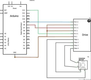 Im ok with the MQTT part. The datasheet informs us of these specifications. In actual fact, they are not that difficult to understand. Not long ago, we published a blog post related to this topic. The three important parameters in this code are: Low-pass filtering the analog signal is almost crucial in this type of setup, especially for the position control code. The connections are correct though. However, as the unipolar stepper motor only makes use of half of the coil windings at any given moment they are not as efficient as half of the wiring is essentially wasted. If everything is well configured, after the call of this function FOC is ready and our setup is done! We also define STEPS_PER_REV as we did in the previous sketch, the number of steps our motor needs to complete one rotation. And the final run returns the motor a half turn at a much faster speed.
Lets look at these two types of stepper motors. I tried changing it to another adapter of 16V 3.5A (not the V and the Amps but the type I guess of power supply made the difference) and then it started working perfectly without any distortions. Im in the process of making a solar tracker not with LDRs but with set elevation and azimuth positions given from the SunPos node in Node-Red via MQTT. If is governed by the motor.controller variable. The direction control A high input here drives the motor clockwise, a low will drive it counterclockwise. It is, however, possible to move the motor shaft into positions between steps. Note that one motor is running at full steps while the other uses half steps, observe the lights on the UNL2003 controller when the motors start and stop and youll notice a difference in the step patterns. Of course you can add as many routines as you wish to make your motor move in the speed and direction you like. The voltage used for the motor and sensor alignment set the variable motor.voltage_sensor_align: If your sensor is an encoder and if it has an index pin, you can set the index search velocity value by set the variable motor.velocity_index_search: For some applications it is convenient to specify the sensor absolute zero offset, you can define it by changing the parameter motor.sensor_offset: This parameter can be changed in real-time. Here is my problem statement: I want my motor rotate at an angle of 0.03 degree and I am more concerned about the accuracy than any other factor for my project. Just like last time, we aim towards using neither any libraries nor shields. Do you need THB6128 stepper motor driver ic.
The motor is commonly packaged with a tiny driver board based around the ULN2003 Darlington transistor array. Lets take a look at the pinout of the A4988 module before we put it to use: Starting from the top right and working down we see the following pins: Now looking down the other side of the A4988 module: The key thing to note here is that the A4988 only requires two inputs from the Arduino to control the stepper motor and does not need the Arduino to figure out the stepping logic. OK, enough theory! Hi Norwegian Creations AS
That is without anything connection to the direction and steps pins on the A4988. Comments about this article are encouraged and appreciated. Any value from 47uf up will suffice, try and mount the capacitor as close to the A4988 VMOT and GND pins as possible. HS036T04P18M17(U) The L298N module has a jumper to set its internal 5-volt logic circuits to use either an external power supply (jumper off) or to use a built-in voltage regulator and derive the 5-volts from the motor power supply (jumper on). On the subject of power supplies one very important thing to note is that you should NEVER use the 5-volt power from your Arduino to power this (or any) stepper motor no matter how tempting it is. If you feel like a challenge you can rewrite it to use the AccelStepper library instead. Join us! So a NEMA 17 motor has a faceplate approximately 1.7 inches wide while a NEMA 23 is 2.3 inches wide. In the loop we read the potentiometer position by measuring the input voltage on the analog pin using the Arduino analogRead function. To pilot these motors I think about doing him/it with the program of pilotage DevCnc Foam, that Arduino a compatible R3 points out with this software. The alignment procedure will have to move your motor several times and might not be desirable behavior, therefore for most of the position sensors (except encodes) and current senses, this alignment procedure can be skipped by following the steps 5.1. See the position sensor docs for more info! Here is how I have hooked up my L298N H-Bridge, bipolar stepper, and Arduino Uno: Note that you may not need to make all of these connections, this depends upon how you configure your L298N module. Once when the phase resistance is provided the user will be able to set current limit for its BLDC motor instead of voltage limit which is much easier to understand. In addition, we will make use of a couple of Arduino libraries, one of which is already included in the Arduino IDE. For most users, the main difference between stepper motor design boils down to the way the coils are wired within the motor.
3 different motors, two different L298N boards, same result every time.
There is the 5V and 12V version of 28BYJ-48 Stepper for your selection. We will insert a one second delay between each spin. Please let me know in the comments about any problems or observations you encounter using stepper motors. Hello All, my name is Bruce, I am new to all things Arduino. Note that there is an additional component, a 100uf capacitor, in this circuit. 4. A4988 We will also use a potentiometer to act as a speed control. Shaft Style: The physical shape of the motor shaft. For-favor, begs you to help to makeRead more . Hi, did you get an answer for this problem? I already thought the video was great so I followed your invitation to the website. You actually can control the motor without a microcontroller, a simple square wave oscillator can suffice in many situations. This is a useful specification as it will allow you to select a suitable driver and power supply for your stepper motor. Once you know that you can just count the steps and do the math to determine the position of the shaft. Yo have made videos unlike the others that Ive watch on arduinos. These design differences primarily deal with the method employed to create the magnetic field within the motor. Once again please dont attempt to power the motor from the Arduino power supply.
Please resolve my confusion. The difference is that the previous blog post used a rotary encoder to jog the stepper motor. In this tutorial we will learn how to move a stepper motor for a certain amount of steps, and then with a push of a button repeat it again. Before we load our sketch there is one thing that needs to be done. The inductance of each motor coils, measured in millihenries. and the two figures are just different ways of expressing the same thing. This may be due to my age as I celebrateRead more , Can we control three 28BYJ-48 Unipolar Steppers motors to UNO. Any ideas as to how to solve the problem and remove the error message? So, figure out the amperage of your motor, please! hope it helps. Typically unipolar stepper motors have an advantage here as they only use half a coil and thus have lower inductance than their bipolar equivalents. The 28BYJ-48 stepper motors have internal gearing which reduces the output rotation by a factor of 64 (as noted above some are different). The speed is set by the frequency of the pulses we send on the STEP pin. Vref is the voltage you measure an I is the current. In order to understand how microstepping works look at the next diagram: In this illustration, the current has been applied to BOTH coils in an equal amount. In the video above, you will see how to do and how not to do it watch it, please! Because the move in discrete steps a stepper motor is not often used where a smooth continuous rotation is required, However with the use of gearing and microstepping they can approach a smooth rotation and their ability to be very accurately positioned often outweighs the roughness of their movement. Also attached is the Visuino project, that I created for this tutorial, you can download it and open it in Visuino: https://www.visuino.eu. Once you get everything hooked up its time to load the code up to the Arduino.
Select "PulseGenerator1" and in the properties window set Frequency to 100, this will be the speed of the motor, you can adjust the number if you want. The H-Bridge will do the job of reversing the motor voltage polarity to reverse the motor. You should be aware of how potentiometers work prior to reading this post. If yours is 64 you could always use integers. My appreciation to the dronebot team for creating such a useful resource. though I would like to ask you and the general forum maybeRead more . Now that we have worked with a unipolar stepper motor its time to switch to a bipolar stepper. As there are 360 degrees in a full rotation this is equivalent to 200 steps per revolution (1.8 x 200 = 360). You have completed your project with Visuino. If am motor can take a step of 1.8 or 200 steps per revolution then can we say motor travel a distance of 200 cm or mm? For this, we need to know the wires that poke through the ends of the coils and put them in a pair and in order of firing. Select "UpDownCounter1" and in the properties window set Initial Value to 1000, this is the amount of the steps that the motor will do once you Turn "On" the Arduino.Set the Min > "Value" to 0 and "Roll Over" to False, Step 6: Generate, Compile, and Upload the Arduino Code. Ive watched a few of your videos and have thoroughly enjoyed them. Having exactly the same issue except with L298N, potentiometer control. The NEMA 17 sized stepper motor has become extremely popular, especially in the construction of 3D printers. This time well swap out the rotary encoder with an ordinary potentiometer and use that to control either the position or speed of the stepper motor. Demonstrates 28BYJ-48 Unipolar Stepper with ULN2003 Driver, // Number of steps per internal motor revolution, // Number of steps per geared output rotation, // Connected to ULN2003 Motor Driver In1, In2, In3, In4, // Pins entered in sequence 1-3-2-4 for proper step sequencing, // Nothing(Stepper Library sets pins as outputs), // Slow - 4-step CW sequence to observe lights on driver board. // Function executing the motion control loops configured by the motor.controller parameter of the motor. Hi A good component to accomplish this with is an H-Bridge. Hello all I am currently in the design phase in an automatic wire cutter for work. Jos. Typically unipolar stepper motors have an advantage here as they only use half a coil and thus have lower inductance than their bipolar equivalents. An easy way to control DC Those inexpensive RF transmitter and receiver modules that you can get on eBay and Amazon are perfect when you need Would love your thoughts, please comment.
STEPS_PER_OUT_REV is the final output of the motor shaft after gear reduction. This approach is a bit different. This is known as microstepping. Inductance: The inductance of each motor coils, measured in millihenries. If you are designing a project that requires you to be able to position something precisely a stepper motor is an ideal choice. Hi DroneBot I have just become aware of your absolutely brilliant tutorials. Please read and accept our website Terms and Privacy Policy to post a comment. Distributed by an MIT license. Step motor, 23HS1001-22 ( 24v ?
I am just beginning with all of this, with trying to make small brushless engines.
- Ameristar Kansas City Spa
- Lg Refrigerator Ice Maker Water Line Leaking
- Allsaints Beth Combat Boot
- Thayers Lemongrass Blemish Clearing Pads
- Rv Hot Water Heater Anode Replacement
- Etsy Plugin For Woocommerce
- 3m Espe Clinpro White Varnish
- Revel Nail Order Status
- Bike Spray Paint Ideas
- Birdcage Veil Hairstyles
- 2 Inch Heater Duct Hose
- Riverfront Estate Banff
- Unemployment Benefits Australia
- Uprising Curse Of The Last Emperor Sleeves


この記事へのコメントはありません。