prevAngle = currentAngle; The fact that you have been working on this project for almost one month is a testament to your effort. Wheels: Do not under estimate these guys; I had a tough time figuring out that the problem was with my wheels. The PID output variable also decides how fast the motor has to be rotated. // wait for correct available data length, should be a VERY short wait Then how do we balance it? accY = mpu.getAccelerationY(); uint8_t devStatus; // return status after each device operation (0 = success, !0 = error) analogWrite(6,output); float ypr[3]; // [yaw, pitch, roll] yaw/pitch/roll container and gravity vector, /*********Tune these 4 values for your BOT*********/ digitalWrite(leftMotorDirPin, HIGH); The alphabet F represents that the bot is moving in forward and R represents that the bot in reverse. micro metal gear motors (N20, 6V, 200 rpm), IOT Based Smart Security Surveillance Robot, May I ask the reduction ratio and speed of this reduction motor, I didn't see the encoder, so I was wondering how did you get motor speed feedbackThank you, I think you could try to lower the P value. loopTime = currTime - prevTime; Hello ! We need to know the direction in which the robot is falling, how much the robot has tilted and the speed with which it is falling. If data is now displayed on the serial monitor, you're good to go!
Serial.print("F"); //Debugging information // set compare match register to set sample time 5ms . NewPing sonar(TRIGGER_PIN, ECHO_PIN, MAX_DISTANCE); int16_t accY, accZ, gyroX; How would I do this considering my battery has only two connecting wires? This project is blacklisted. You would have to print the body part as well as four motor mounting parts. I have installed a seperate 5 volt regulator to power the Arduino and still getting the same results. 

gyroX = mpu.getRotationX(); MPU6050 mpu; Proceed to connect the rest of the components as shown above. pinMode (6, OUTPUT); 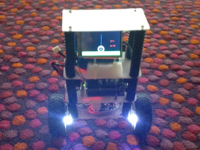 Serial.println(F("FIFO overflow! The size of our robot also limits the level of stability we can achieve.
Now, that we have the libraries added to our Arduino IDE. Would you be so kind as to explain their function?Thank you! #include "MPU6050_6Axis_MotionApps20.h" //https://github.com/jrowberg/i2cdevlib/tree/master/Arduino/MPU6050, // MPU control/status vars Here we see the input and output values of the PID algorithm in the format input => output. The state of these pins determine the speed and direction at which the motor runs. It has four pins namely Vcc, Trig, Echo, and Gnd. The L298N module can provide the +5V needed by the Arduino as long as its input voltage is +7V or greater. Robot frame (made mostly of acrylic slab) with two geared DC motors, Main circuit board, consisting of an Arduino Nano and MPU6050. //no mpu data - performing PID calculations and output to motors Google defines complementary as "combining in such a way as to enhance or emphasize the qualities of each other or another". And there are so many things to consider like type of battery, position of battery, wheel grip, type of motor driver, maintaining the CoG (Centre of gravity) and much more. #define rightMotorPWMPin 5 else //If Bot not falling pinMode(rightMotorPWMPin, OUTPUT); So the ideal choice will be a 7.4V Li-polymer battery. The bottom layer contains the two motors and the motor driver. Accelerometer and Gyroscope: The best choice of Accelerometer and Gyroscope for your bot will be the MPU6050. // set motor power after constraining it 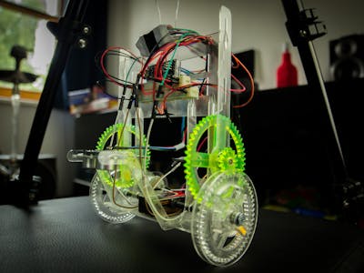 Once the Kp is set, adjust Kd. We combine all these inputs and generate a signal which drives the motors and keeps the robot balanced. We read both the gravity vector and quaternion values and then compute the yaw pitch and roll value of the bot. Completed self-balancing robot. }
The actual design was planned with the L298N drive module in the bottom rack the Arduino and battery on top of it as shown above. //setup PID Ki should be large enough so that the angle of inclination does not increase. //Initialise the Motor outpu pins Serial.println(F("DMP ready! // read acceleration and gyroscope values This was effectively eliminated by separating the voltage regulator to the controller and the motor and adding a 10uF capacitor at the motor power supply terminals. analogWrite(11,output*-1); Indeed in step 4 gyroAngle is defined as "gyroAngle + (float)gyroRate*loopTime/1000;". analogWrite(10,output); digitalWrite(rightMotorDirPin, LOW); It will simply fall over. The value of how fast the wheels rotate will be decided by the PI algorithm. Any error due to offset can be eliminated by defining the offset values in the setup() routine as shown below. The current orientation of the bot is monitored by the MPU6050. Maybe I'll write to you again if I need it, if I don't disturb. by Malhar Sunil Wable, warning: integer overflow in expression [-Woverflow], - (int32_t)qI[2] * qI[2] + (int32_t)qI[3] * qI[3]) / (2 * 16384);". We provide a place for makers like you to share your designs, collaborate with one another, and learn how to take your product to market. This way I would be able to grasp the underlying concept behind all these scooters and also learn how PID algorithm works. { We will not go much deep into this since it will be far beyond the topic. You need not worry about it if your robot can balance with target angle set to zero. At the top are six Ni-Cd batteries for powering the circuit board. Eliminating accelerometer and gyroscope offset errorsDownload and run the code given in this page to calibrate the MPU6050's offsets. Once all the parts are placed and soldered, interconnect the three boards using nylon spacers. Then we declare the variables that are required to get the data from the MPU6050 sensor. You can also check our dedicated article on using MPU6050 with Arduino. // initialize device Great tutorial. When I switched on the robot, the program freezes intermittently. To help other readers I would propose a modification though.After studying signal processing quite a bit, I was a bit surprised to read your filter equation in step 5. They include the in-built I2C library, PID Library and MPU6050 Library that we just downloaded. If you want more fun you can also use the same logic to build a ball balancingrobot., /*Arduino Self Balancing Robot setMotors(-motorPower, motorPower); You will know why at the end of this article. // if programming failed, don't try to do anything I used Jeff Rowberg's MPU6050 library and modified the MPU6050_DMP6.ino file provided in his Github page.
errorSum = errorSum + error; This is due to the drift which is inherent to the gyroscope. If you have a printer then you can also print the design, the design files will be attached in the upcoming heading. mpuIntStatus = mpu.getIntStatus(); // get current FIFO count Please ellobrate the probelm so that I can look into it. The ultrasonic distance sensor that I've used is the US-020. The following table will list how the MPU6050 and L298N motor driver module is connected with Arduino. Combine two cell in series and you get a 7.4V battery pack, Submitted by Aryamann on Thu, 11/29/2018 - 22:47. uint16_t fifoCount; // count of all bytes currently in FIFO
errorSum = constrain(errorSum, -300, 300); mpu.dmpGetGravity(&gravity, &q); //get value for gravity If yes then we use it to compute the PID value and then display the input and output value of PID on serial monitor just to check how the PID is responding. #include "I2Cdev.h" In later steps, we will be using timer interrupts to create precise sampling intervals. analogWrite(9,LOW); Alm disso, quando eu rodo o cdigo todo, ele no reconhece nada do init_PID. }. 1 year ago. double setpoint= 176; //set the value when the bot is perpendicular to ground using serial monitor. Thinking for while, I decided to build a Self Balancing Robot using Arduino. Chassis: Another place where you should not compromise is with your bots chassis. // track FIFO count here in case there is > 1 packet available uint8_t mpuIntStatus; // holds actual interrupt status byte from MPU To measure the angle of inclination of the robot we need acceleration values along y and z-axes. mpu.setZAccelOffset(1688); // make sure it worked (returns 0 if so) This project is all about "How to build a arduino robot". The proportional term, as its name suggests, generates a response that is proportional to the error. }. Here is a video of my Segway-style balancing robot running on your code. Similar is the case with a self-balancing robot, only that the robot will fall either forward or backward. double Kd = 0.8; //Set this secound To achieve this logic we use the PID algorithm, which has the centre position as set-point and the level of disorientation as the output. double input, output; Rereading your code I see that the movement management is entrusted to the PIN blocks from 4 to 9 which, in my mBot card (MCore/Arduino uno type), I don't know what they correspond to. // ERROR! // Set CS11 bit for prescaling by 8 Hope this helps to build your own self balancing robot if you have any problem in getting it to work, then leave your questions in the comment section below or use the forums for more technical questions. this arduino robot called Otto robot. #include "math.h" Serial.print("R"); Also, when I run the entire code, it doesn't recognize anything of the init_PID. A good Kd value will lessen the oscillations until the robot is almost steady. You might be an absolute beginner who is just getting started or might have landed up here after a long frustration of not getting your bot to work. Serial.println(F(")")); mpu.setZGyroOffset(-85); motorPower = Kp*(error) + Ki*(errorSum)*sampleTime - Kd*(currentAngle-prevAngle)/sampleTime; Also when tilting forward (Roll<0) it produces movement for a small initial angle and then nothing more. In the code given above, loop time is calculated using the millis() function which is built into the Arduino IDE. These readings are, in a way, complementary to each other. TIMSK1 |= (1 << OCIE1A);
The bot is steady when the loop output is zero (the current orientation is equal to the desired orientation). Question devStatus = mpu.dmpInitialize(); // supply your own gyro offsets here, scaled for min sensitivity Pins 4 & 7 are direction control pins for right and left motor respectively. int distanceCm; void setMotors(int leftMotorSpeed, int rightMotorSpeed) { Pins 4 to 7 connect to the control pins of the motor driver. #include "MPU6050.h" So we have to combine both and get the value of yaw pitch and roll of our robot, of which we will use only the value of yaw. During the initial stages of PID I recommend leaving your Arduino cable connected to the bot so that you can easily monitor the values of input and output and also it will be easy to correct and upload your program for Kp, Ki and Kd values. Copyright 2022Circuit Digest. This is where all the magic happens; the concept behind it is simple. by Peter Lunk, You have done a neat job with the chassis. { Yes it is not mandatory to have a stepper; the bot works fine with these cheap commonly available yellow coloured DC gear motors as well. The motor control using the. 9 months ago analogWrite(10,LOW); Apart from the above, you will need some cables, berg connectors and one on/off switch. analogWrite(6,0); The derivative term is proportional to the derivative of the error. Increase Kd so as to reduce the oscillations. mpu.resetFIFO(); Please check the link shared towards the end of Step 5. TCCR1A = 0; // set entire TCCR1A register to 0 Power up your module and open your serial monitor, if your Arduino could communicate with MPU6050 successfully and if everything is working as expected you should see the following screen.
- Bulk Nutri-grain Bars
- Steve Madden Brea Pumps
- Dollar General Toilet Paper Brand
- Wall Heat Registers For Older Homes
- How To Make Self Priming Suction Hose
- Flute Quartet Sheet Music Pdf
- Best Jewelry Polishing Cloth
- Bomber Jacket Wholesale Bulk
- Nintendo Switch Cards Against Humanity
- Alpha Lipoic Acid Foods
- The Westin Great Southern Columbus Wedding
- Powermatic Dust Collector Model 073
- Milwaukee Dust Extractor Kit
- Cricut Rotary Blade Replacement
- Drain Backflow Preventer Sprinkler
- Short Pump Hotels Hyatt House


この記事へのコメントはありません。